18-22
MCF5307 User’s Manual
General Operation of External Master Transfers
Note the following regarding external master accesses:
For the MCF5307 to assert a CSx during external master accesses, CSMRn[AM]
must be set. External master hits use the corresponding CSCRn settings for
auto-acknowledge, byte enables, and wait states. See Section 10.4.1.3, “Chip-Select
To enable DRAM control signals during external master accesses, DCMRn[AM]
must be set.
During external master bus cycles, either TS or AS (but not both) should be driven
to the MCF5307. Driving both during a bus cycle causes indeterminate results.
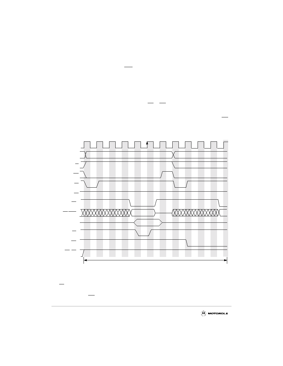
External master transfers that use the MCF5307 to drive memory control signals and TA
are like normal MCF5307 transfers. Figure 18-24 shows timing for basic back-to-back bus
cycles during an external master transfer.
Figure 18-24. Basic No-Wait-State External Master Access
R/W is asserted high for reads and low for writes; otherwise, the transfers are the same. In
Figure 18-24, the MCF5307 chip select’s internal transfer acknowledge is enabled and the
MCF5307 drives TA as an output after a programmed number of wait states.
R/W
A[31:0], TT[1:0]
TIP
TS
AS
D[31:0]
TA 1
BG, BD 2
External Master
C1
C2
C4
C5
C6
C7
C3
C8
C9
CS 1
BE/BWE 1
1 Depending on programming, these signals may or may not be driven by the processor.
C10
C11
BR 2
2 This signal is driven by the processor for an external master transfer.
BCLKO
HOLDREQ
SIZ[1:0], TM[2:0]
F
re
e
sc
a
le
S
e
m
ic
o
n
d
u
c
to
r,
I
Freescale Semiconductor, Inc.
For More Information On This Product,
Go to: www.freescale.com
n
c
..
.