- 您現(xiàn)在的位置:買賣IC網(wǎng) > PDF目錄67987 > MCP7940NT-I/SN REAL TIME CLOCK, PDSO8 PDF資料下載
參數(shù)資料
| 型號: | MCP7940NT-I/SN |
| 元件分類: | 時鐘/數(shù)據(jù)恢復及定時提取 |
| 英文描述: | REAL TIME CLOCK, PDSO8 |
| 封裝: | 3.90 MM, ROHS COMPLIANT, PLASTIC, SOIC-8 |
| 文件頁數(shù): | 36/36頁 |
| 文件大小: | 551K |
| 代理商: | MCP7940NT-I/SN |
第1頁第2頁第3頁第4頁第5頁第6頁第7頁第8頁第9頁第10頁第11頁第12頁第13頁第14頁第15頁第16頁第17頁第18頁第19頁第20頁第21頁第22頁第23頁第24頁第25頁第26頁第27頁第28頁第29頁第30頁第31頁第32頁第33頁第34頁第35頁當前第36頁
2011 Microchip Technology Inc.
DS25010A-page 9
MCP7940N
4.0
RTCC FUNCTIONALITY
The MCP7940N family is a highly integrated RTCC.
On-board time and date counters are driven from a low-
power oscillator to maintain the time and date. An
integrated VCC switch enables the device to maintain
the time and date and also the contents of the SRAM
during a VCC power failure.
4.1
RTCC MEMORY MAP
The RTCC registers are contained in addresses
0x00h-0x1fh. 64 bytes of user-accessable SRAM are
located in the address range 0x20-0x5f. The SRAM
memory is a separate block from the RTCC control
and Configuration registers. All SRAM locations are
battery-backed-up during a VCC power fail. Unused
locations are not accessible, MCP7940N will noACK
after the address byte if the address is out of range.
The shaded areas are not implemented and read as
‘0’. No error checking is provided when loading time
and date registers.
Addresses 0x00h-0x06h are the RTCC Time and
Date registers. These are read/write registers.
Care must be taken when accessing these regis-
ters while the oscillator is running.
Incorrect data can appear in the Time and Date
registers if a write is attempted during the time
frame where these internal registers are being
incremented. The user can minimize the likeli-
hood of data corruption by ensuring that any
writes to the Time and Date registers occur before
the contents of the second register reach a value
of 0x59H.
Addresses 0x07h-0x09h are the device Configu-
ration and Calibration.
Addresses 0x0Ah-0x10h are the Alarm 0 regis-
ters. These are used to set up the Alarm 0, the
Interrupt polarity and the Alarm 0 compare.
Addresses 0x11h-0x17h are the same as 0x0Bh-
0x11h but are used for Alarm 1.
Addresses 0x18h-0x1Fh are used for the time-
stamp feature.
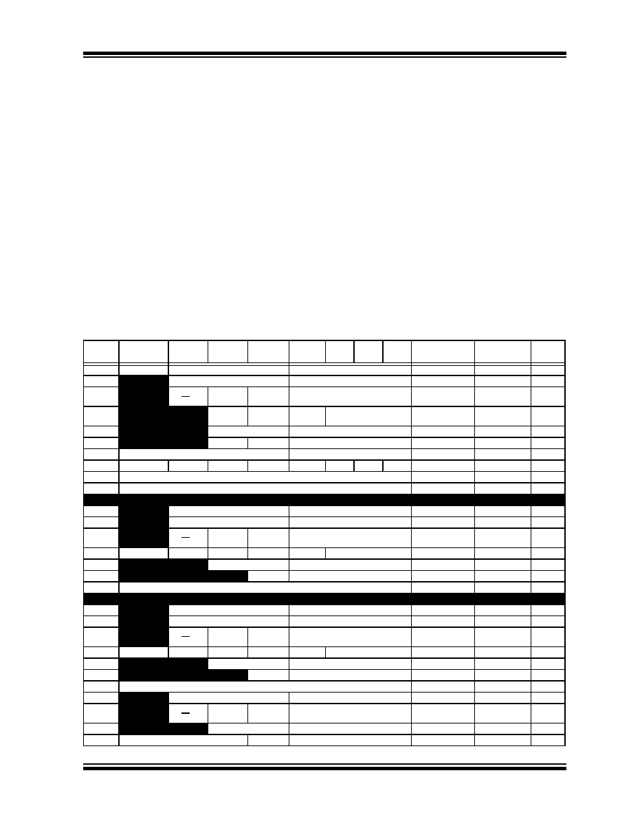
The Memory Map is shown in Table 4-1.
TABLE 4-1:
RTCC MEMORY MAP
Address
Bit 7
Bit 6
Bit 5
Bit 4
Bit 3
Bit 2
Bit 1
Bit 0
Function
Range
Reset
State
00h
ST
10 Seconds
Seconds
00-59
00h
01h
10 Minutes
Minutes
00-59
00h
02h
12/24
10 Hour
AM/PM
10 Hour
Hour
Hours
1-12 + AM/PM
00 - 23
00h
03h
OSCON
VBAT
VBATEN
Day
1-7
01h
04h
10 Date
Date
01-31
01h
05h
LP
10 Month
Month
01-12
01h
06h
10 Year
Year
00-99
01h
07h
OUT
SQWE
ALM1
ALM0
EXTOSC
RS2
RS1
RS0
Control Reg.
80h
08h
CALIBRATION
Calibration
00h
09h
RESERVED – DO NOT USE
00h
0Ah
10 Seconds
Seconds
00-59
00h
0Bh
10 Minutes
Minutes
00 - 59
00h
0Ch
12/24
10 Hour
AM/PM
10 Hours
Hour
Hours
1-12 + AM/PM
00-23
00h
0Dh
ALM0POL
ALM0C2
ALM0C1
ALM0C0
ALM0IF
Day
1-7
01h
0Eh
10 Date
Date
01-31
01h
0Fh
10 Month
Month
01-12
01h
10h
Reserved – Do not use
Reserved
01h
11h
10 Seconds
Seconds
00-59
00h
12h
10 Minutes
Minutes
00-59
00h
13h
12/24
10 Hour
AM/PM
10 Hours
Hour
Hours
1-12 + AM/PM
00-23
00h
14h
ALM1POL
ALM1C2
ALM1C1
ALM1C0
ALM1IF
Day
1-7
01h
15h
10 Date
Date
01-31
01h
16h
10 Month
Month
01-12
01h
17h
Reserved – Do not use
Reserved
01h
18h
10 Minutes
Minutes
00h
19h
12/24
10 Hour
AM/PM
10 Hours
Hour
00h
1Ah
10 Date
Date
00h
1Bh
Day
10 Month
Month
00h
相關PDF資料 |
PDF描述 |
|---|---|
| MCP7940NT-I/MS | REAL TIME CLOCK, PDSO8 |
| MCP79411-I/SN | REAL TIME CLOCK, PDSO8 |
| MCP79411-I/MNY | REAL TIME CLOCK, PDSO8 |
| MCP79410-I/ST | REAL TIME CLOCK, PDSO8 |
| MCP79411-I/MS | REAL TIME CLOCK, PDSO8 |
相關代理商/技術參數(shù) |
參數(shù)描述 |
|---|---|
| MCP79410 | 制造商:MICROCHIP 制造商全稱:Microchip Technology 功能描述:I2C? Real-Time Clock/Calendar with EEPROM, SRAM, Unique ID and Battery Switchover |
| MCP79410_13 | 制造商:MICROCHIP 制造商全稱:Microchip Technology 功能描述:Battery-Backed I2Ca?¢ Real-Time Clock/Calendar with EEPROM and Unique ID |
| MCP79410-I/MNY | 制造商:Microchip Technology Inc 功能描述:I2C GP RTCC, 1KB EE, 64B SRAM, ID - Rail/Tube |
| MCP79410-I/MS | 功能描述:實時時鐘 I2C GP RTCC 1Kb EE 64B SRAM ID RoHS:否 制造商:Microchip Technology 功能:Clock, Calendar. Alarm RTC 總線接口:I2C 日期格式:DW:DM:M:Y 時間格式:HH:MM:SS RTC 存儲容量:64 B 電源電壓-最大:5.5 V 電源電壓-最小:1.8 V 最大工作溫度:+ 85 C 最小工作溫度: 安裝風格:Through Hole 封裝 / 箱體:PDIP-8 封裝:Tube |
| MCP79410-I/P | 制造商:Microchip Technology Inc 功能描述:I2C GP RTCC, 1KB EE, 64B SRAM, ID - Rail/Tube 制造商:Microchip Technology Inc 功能描述:RTCC 12C 1K EE 64B SRAM 8PDIP |
發(fā)布緊急采購,3分鐘左右您將得到回復。