- 您現(xiàn)在的位置:買賣IC網(wǎng) > PDF目錄359155 > MCZ146010EG (飛思卡爾半導(dǎo)體(中國(guó))有限公司) Low Power CMOS Photoelectric Smoke Detector IC PDF資料下載
參數(shù)資料
| 型號(hào): | MCZ146010EG |
| 廠商: | 飛思卡爾半導(dǎo)體(中國(guó))有限公司 |
| 英文描述: | Low Power CMOS Photoelectric Smoke Detector IC |
| 中文描述: | 低功耗CMOS集成電路光電感煙探測(cè)器 |
| 文件頁數(shù): | 3/18頁 |
| 文件大?。?/td> | 391K |
| 代理商: | MCZ146010EG |

Sensors
Freescale Semiconductor
3
MC146010
This device contains protection circuitry to guard against
damage due to high static voltages or electric fields.
However, precautions must be taken to avoid applications of
voltages any higher than maximum rated voltages to this
high-impedance circuit. For proper operation, V
IN
and V
OUT
should be constrained to a range of V
SS
≤
(V
IN
or
V
OUT
)
≤
V
DD
except for I/O pin which can exceed V
DD
, and
the Test/Mute input, which can go below V
SS
.
Unused inputs must always be tied to an appropriate logic
voltage level (e.g. either V
SS
or V
DD
). Unused outputs and/or
an unused I/O must be left open.
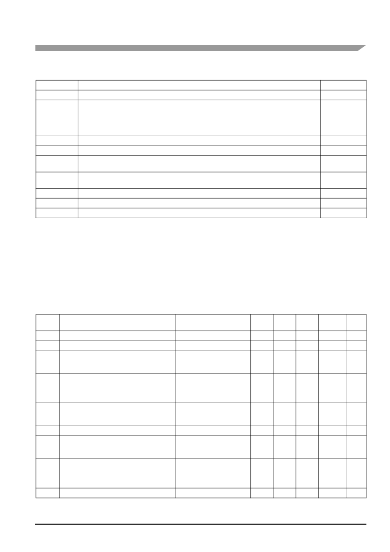
Table 1. Maximum Ratings
(1)
(Voltages Referenced to V
SS
)
1. Maximum ratings are those values beyond which damage to the device may occur. Functional operation should be restricted to the limits in
the electrical characteristics tables.
2. Derating: -12 mW/°C from 25°C to 60°C.
3. Derating: -3.5 mW/°C from 25°C to 60°C.
Symbol
Parameter
Value
Unit
V
DD
DC Supply Voltage
-0.5 to +12
V
V
IN
DC Input Voltage
C1, C2, Detect
Osc, Low-Supply Trip
I/O
Feedback
Test
-0.25 to V
DD
+0.25
-0.25 to V
DD
+0.25
-0.25 to V
DD
+10
-15 to +25
-1.0 to V
DD
+0.25
±10
V
I
IN
I
OUT
I
DD
DC Input Current, per Pin
mA
DC Output Current, per Pin
±25
mA
DC Supply Current, V
DD
/V
SS
pins
(15 Seconds in Reverse Dir.)
+25 Forward
-150 Reverse
mA
P
D
Power Dissipation
in Stil Air, 5 sec.
Continuous
1200
(2)
350
(3)
mW
T
stg
Storage Temperature
-55 to +125
°C
T
A
Operating Temperature
-25 to +75
°C
T
L
Lead Temperature, 1 mm from case for 10 seconds
260
°C
Table 2. Electrical Characteristics
(Voltages Referenced to V
SS
, T
A
= -10 to 60
°
C unless otherwise indicated.)
Symbol
Parameter
Test Condition
Test
Pin
V
DD
Min
Max
Unit
V
DD
Power Supply Voltage Range
—
—
6.0
12
V
V
TH
Supply Threshold Voltage, Low Supply Alarm
Low Supply Trip: V
IN
= V
DD
/3
15
—
7.2
7.8
V
I
DD
Average Operating Supply Current
(per Package)
(Does not include Current through D3-IR Emitter)
Standby
Configured per
Figure 5
—
—
12
9.0
—
—
9.0
7.0
μA
I
DD
Peak Supply Current (per Package)
(Does not include IRED Current into base of Q1)
During Strobe On, IRED Off
Configured per
Figure 5
During Strobe On, IRED On
Configured per
Figure 5
—
—
12
12
—
—
1.25
2.5
mA
V
IL
Low Level Input Voltage
I/O
Feedback
Test
7.0
10
16
9.0
9.0
9.0
—
—
—
1.5
2.7
0.5
V
V
IM
Mid Level Input Voltage
Test
16
9.0
2.0
V
DD
-2.0
V
V
IH
High Level Input Voltage
I/O
Feedback
Test
7.0
10
16
9.0
9.0
9.0
3.2
6.3
8.5
—
—
—
V
I
IN
Input Current
OSC, Detect
Low-Supply Trip
Feedback
Test
V
IN
= V
SS
or V
DD
V
IN
= V
SS
or V
DD
V
IN
= V
SS
or V
DD
V
IN
= V
SS
or V
DD
3.12
15
10
16
12
12
12
12
-100
-100
-100
-100
+100
+100
+100
+100
nA
I
IL
Test Mode Input Current
V
IN
= V
SS
or V
DD
16
12
-100
-1.0
μ
A
相關(guān)PDF資料 |
PDF描述 |
|---|---|
| MCZ146012EG | Low Power CMOS Photoelectric Smoke Detector IC |
| MCZ33099CEG | Adaptive Alternator Voltage Regulator |
| MCZ33198EF | Automotive High-Side TMOS Driver |
| MCZ33199EF | Automotive ISO 9141 Serial Link Driver |
| MCZ33285EF | Dual High-Side TMOS Driver |
相關(guān)代理商/技術(shù)參數(shù) |
參數(shù)描述 |
|---|---|
| MCZ146010EGR2 | 制造商:FREESCALE 制造商全稱:Freescale Semiconductor, Inc 功能描述:Low Power CMOS Photoelectric Smoke Detector IC |
| MCZ146012EG | 制造商:FREESCALE 制造商全稱:Freescale Semiconductor, Inc 功能描述:Low Power CMOS Photoelectric Smoke Detector IC |
| MCZ146012EGR2 | 制造商:FREESCALE 制造商全稱:Freescale Semiconductor, Inc 功能描述:Low Power CMOS Photoelectric Smoke Detector IC |
| MCZ2010AH | 制造商:TDK 制造商全稱:TDK Electronics 功能描述:Common Mode Filters For high-speed differential signal line |
| MCZ2010AH121 | 功能描述:電磁干擾濾波珠子、扼流圈和陣列 120ohms 25% 2 Line RoHS:否 制造商:AVX 阻抗: 最大直流電流:35 mA 最大直流電阻: 容差: 端接類型:SMD/SMT 電壓額定值:25 V 工作溫度范圍:- 25 C to + 85 C 封裝 / 箱體:0603 (1608 metric) |
發(fā)布緊急采購(gòu),3分鐘左右您將得到回復(fù)。