- 您現(xiàn)在的位置:買賣IC網(wǎng) > PDF目錄383598 > MFT62340-J (Mitel Networks Corporation) Parallel Fiber Transmitter(用于并行光纖的高速傳送器) PDF資料下載
參數(shù)資料
| 型號(hào): | MFT62340-J |
| 廠商: | Mitel Networks Corporation |
| 英文描述: | Parallel Fiber Transmitter(用于并行光纖的高速傳送器) |
| 中文描述: | 并行光纖發(fā)射器(用于并行光纖的高速傳送器) |
| 文件頁數(shù): | 4/9頁 |
| 文件大?。?/td> | 509K |
| 代理商: | MFT62340-J |
MFT62340-J
Preliminary Information
4
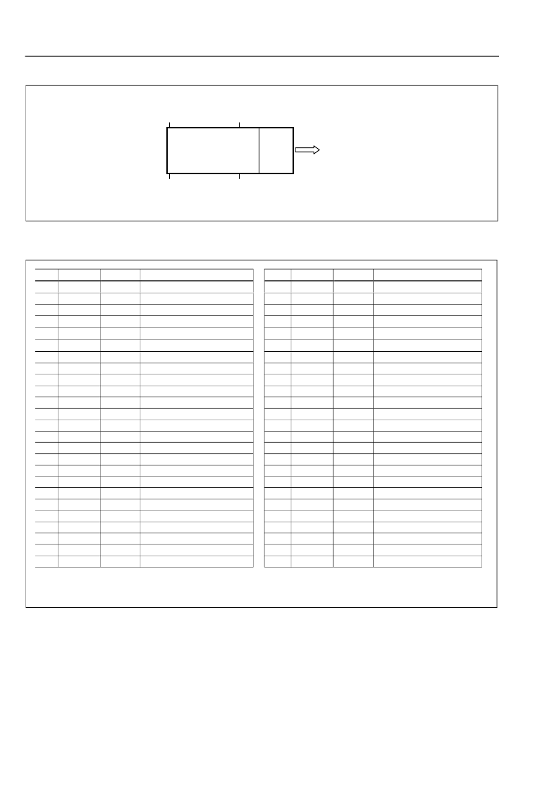
Figure 5 - Pin Assignment (Top View)
Pin Description
1
25
26
50
F
C
FIBER RIBBON
1
12
MFT62340-J
No
1
2
3
4
5
6
7
8
9
10
11
12
13
14
15
16
17
18
19
20
21
22
23
24
25
1
High = Lasers active. Internal pull-down resistor 50k
.
2
Low = Driver not ready. Open drain with internal pull-up resistor 10k
.
Name
Gnd
V
CC
V
CC
V
EN1
4
V
EN5
8
V
12
Gnd
DI1C
DI1
Gnd
DI2C
DI2
Gnd
DI3C
DI3
Gnd
DI4C
DI4
Gnd
DI5C
DI5
Gnd
DI6C
DI6
Gnd
Logic
Description
Ground
Positive power supply
Positive power supply
VCSELs enable ch. 1-4
VCSELs enable ch. 5-8
VCSELs enable ch. 9-12
Ground
Data input No 1, inv.
Data input No 1.
Ground
Data input No 2, inv.
Data input No 2.
Ground
Data input No 3, inv.
Data input No 3.
Ground
Data input No 4, inv.
Data input No 4.
Ground
Data input No 5, inv.
Data input No 5.
Ground
Data input No 6, inv.
Data input No 6.
Ground
No
50
49
48
47
46
45
44
43
42
41
40
39
38
37
36
35
34
33
32
31
30
29
28
27
26
Name
Gnd
V
CC
V
NFLT
Logic
Description
Ground
Positive power supply
Positive power supply
Fault detection
Not Connected
Not Connected
Ground
Data input No 12.
Data input No 12, inv.
Ground
Data input No 11.
Data input No 11, inv.
Ground
Data input No 10.
Data input No 10, inv.
Ground
Data input No 9.
Data input No 9, inv.
Ground
Data input No 8.
Data input No 8, inv.
Ground
Data input No 7.
Data input No 7, inv.
Ground
CMOS
CMOS
CMOS
1
NMOS
2
1
1
Gnd
DI12
DI12C
Gnd
DI11
DI11C
Gnd
DI10
DI10C
Gnd
DI9
DI9C
Gnd
DI8
DI8C
Gnd
DI7
DI7C
Gnd
CML
CML
CML
CML
CML
CML
CML
CML
CML
CML
CML
CML
CML
CML
CML
CML
CML
CML
CML
CML
CML
CML
CML
CML
相關(guān)PDF資料 |
PDF描述 |
|---|---|
| MGAD | Hybrid Pulsed Laser Module |
| MGAD1S0607 | Hybrid Pulsed Laser Module |
| MGAD2S0607 | Hybrid Pulsed Laser Module |
| MGAD3S0607 | Hybrid Pulsed Laser Module |
| MGF1402B | LOW NOISE GaAs FET |
相關(guān)代理商/技術(shù)參數(shù) |
參數(shù)描述 |
|---|---|
| MFT62346501 | 制造商:LG Corporation 功能描述:Name Plate |
| MFT62346506 | 制造商:LG Corporation 功能描述:Name Plate |
| MFT62346508 | 制造商:LG Corporation 功能描述:NAME PLATE |
| MFT62346509 | 制造商:LG Corporation 功能描述:Name Plate |
| MFT62366501 | 制造商:LG Corporation 功能描述:NAME PLATE |
發(fā)布緊急采購(gòu),3分鐘左右您將得到回復(fù)。