- 您現(xiàn)在的位置:買賣IC網 > PDF目錄359163 > MGA-53543-TR2 (AGILENT TECHNOLOGIES INC) 50 MHz - 6000 MHz RF/MICROWAVE WIDE BAND LOW POWER AMPLIFIER PDF資料下載
參數資料
| 型號: | MGA-53543-TR2 |
| 廠商: | AGILENT TECHNOLOGIES INC |
| 元件分類: | 放大器 |
| 英文描述: | 50 MHz - 6000 MHz RF/MICROWAVE WIDE BAND LOW POWER AMPLIFIER |
| 封裝: | PLASTIC, SC-70, SOT-343, 4 PIN |
| 文件頁數: | 7/14頁 |
| 文件大?。?/td> | 181K |
| 代理商: | MGA-53543-TR2 |
7
specific impedances (
Γ
and
Γ
L
)
to the device. It is also possible
to match this part for best NF or
best gain. However, this will
impact the IP3 performance. To
achieve best noise figure, the
input match will need to be
modified to present gamma opt
to the device. To achieve the best
gain will require both the input
and output to be conjugately
matched (which will also result
in the best return loss). Where
needed, the match presented to
the input and the output of the
device can be modified to com-
promise between IP3, NF and
gain performance.
The MGA-53543 has isolation
large enough to allows input and
output reflection coefficients to
be replaced by S11 and S22.
In general matching for minimum
noise figure does not necessarily
guarantee good IP3 performance
nor does it guarantee good gain.
This is due to the fact that the
impedance parameters shown
below in Table 2 are not guaran-
teed to lie near each other on a
Smith Chart. So, ideally if all
input matching parameters lied
near each other or at the same
point, and all output parameters
also lied near each other or at the
same point, the amplifier would
have minimum Noise Figure,
maximum IP3 and maximum
Gain all with a single match.
Typically this is not the case and
some parameter must be sacri-
ficed to improve another. Table 2
briefly lists the input and output
parameters required for each
type of match while Figure 4
depicts how each is defined.
Match
for
Input
Tuning
Output
Tuning
IP3
Γ
s
Γ
L
NF
Γ
opt
none
RL
in
S11*
none
RL
out
none
S22*
Gain
S11*
S22*
Table 2. Required matching for NF, IP3, input &
output Return Loss and Gain.
50
S22*
Γ
L
S22
Γ
L
*
50
Input
Match
Output
Match
53
S11
Γ
S
*
S11*
Gain
IP3
NF
Γ
S
Γ
opt
*
Γ
opt
Figure 4. Definition of matching parameters.
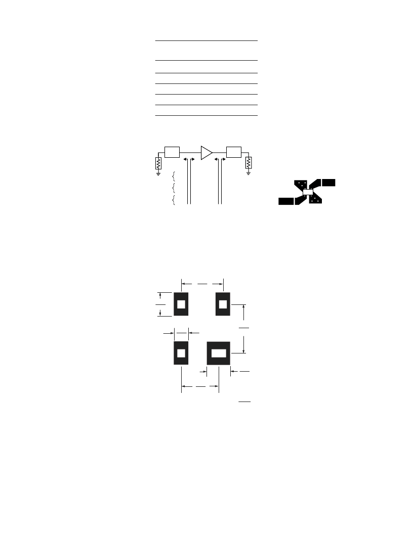
PCB Layout
A recommended PCB pad layout
for the miniature SOT-343
(SC-70) package used by the
MGA-53543 is shown in Figure 5.
1.30
0.051
0.60
0.024
0.9
0.035
Dimensions in
mm
inches
1.15
0.045
2.00
0.079
1.00
0.039
Figure 5. Recommended PCB Pad Layout for
Agilent’s SC70 4L/SOT-343 Products.
This layout provides ample
allowance for package placement
by automated assembly equip-
ment without adding parasitics
that could impair the high
frequency RF performance of the
MGA-53543. The layout is shown
with a footprint of a SOT-343
package superimposed on the
PCB pads for reference.
A microstrip layout with sufficient
ground vias as shown in Figure 6
is recommended for the
MGA-53543 in transitioning from a
package pad layout as in Figure 5.
53
RF
OUTPUT
RF
INPUT
Figure 6. Microstripline Layout.
RF Grounding
Adequate grounding of Pins 1 and
4 of the RFIC are important to
maintain device stability and RF
performance. Each of the ground
pins should be connected to the
ground plane on the backside of
the PCB by means of plated
through holes (vias). The ground
vias should be placed as close to
the package terminals as practical
to reduce inductance in ground
path. It is good practice to use
multiple vias to further minimize
ground path inductance.
PCB Materials
FR-4 or G-10 type material is a
good choice for most low cost
wireless applications using single
or multi-layer printed circuit
boards. Typical single-layer
board thickness is 0.020 to 0.031
inches. Circuit boards thicker
than 0.031 inches are not recom-
mended due to excessive induc-
tance in the ground vias.
相關PDF資料 |
PDF描述 |
|---|---|
| MGA-81563-TR1 | 0.1- 6 GHz 3 V, 14 dBm Amplifier |
| MGA-82563-TR1 | 0.1-6 GHz 3V, 17 dBm Amplifier |
| MGB2310TK-X | 128 x 64 pixel format, LED or EL Backlight available |
| MGB27TA-X | ULTRA HIGH BRIGHTNESS GREEN LED LAMP |
| MGB31TA-X | ULTRA HIGH BRIGHTNESS GREEN LED LAMP |
相關代理商/技術參數 |
參數描述 |
|---|---|
| MGA-53543-TR2G | 功能描述:射頻放大器 5 SV 15.4 dB RoHS:否 制造商:Skyworks Solutions, Inc. 類型:Low Noise Amplifier 工作頻率:2.3 GHz to 2.8 GHz P1dB:18.5 dBm 輸出截獲點:37.5 dBm 功率增益類型:32 dB 噪聲系數:0.85 dB 工作電源電壓:5 V 電源電流:125 mA 測試頻率:2.6 GHz 最大工作溫度:+ 85 C 安裝風格:SMD/SMT 封裝 / 箱體:QFN-16 封裝:Reel |
| MGA-53589 | 制造商:AVAGO 制造商全稱:AVAGO TECHNOLOGIES LIMITED 功能描述:50MHz to 3GHz High Linear Amplifier Lead-free Option Available |
| MGA-53589-BLKG | 功能描述:射頻放大器 Amplifier RFIC GaAs RoHS:否 制造商:Skyworks Solutions, Inc. 類型:Low Noise Amplifier 工作頻率:2.3 GHz to 2.8 GHz P1dB:18.5 dBm 輸出截獲點:37.5 dBm 功率增益類型:32 dB 噪聲系數:0.85 dB 工作電源電壓:5 V 電源電流:125 mA 測試頻率:2.6 GHz 最大工作溫度:+ 85 C 安裝風格:SMD/SMT 封裝 / 箱體:QFN-16 封裝:Reel |
| MGA-53589-TR1G | 功能描述:射頻放大器 Amplifier RFIC GaAs RoHS:否 制造商:Skyworks Solutions, Inc. 類型:Low Noise Amplifier 工作頻率:2.3 GHz to 2.8 GHz P1dB:18.5 dBm 輸出截獲點:37.5 dBm 功率增益類型:32 dB 噪聲系數:0.85 dB 工作電源電壓:5 V 電源電流:125 mA 測試頻率:2.6 GHz 最大工作溫度:+ 85 C 安裝風格:SMD/SMT 封裝 / 箱體:QFN-16 封裝:Reel |
| MGA-545P8 | 制造商:Avago Technologies 功能描述:IC AMP RF E-PHEMT LPCC8 3.3V 制造商:Avago Technologies 功能描述:IC, AMP, RF E-PHEMT, LPCC8, 3.3V |
發(fā)布緊急采購,3分鐘左右您將得到回復。