- 您現(xiàn)在的位置:買賣IC網(wǎng) > PDF目錄296568 > ML235RAG26NGLC (COILCRAFT INC) 1 ELEMENT, 0.026 uH, CERAMIC-CORE, GENERAL PURPOSE INDUCTOR, SMD PDF資料下載
參數(shù)資料
| 型號: | ML235RAG26NGLC |
| 廠商: | COILCRAFT INC |
| 元件分類: | 通用定值電感 |
| 英文描述: | 1 ELEMENT, 0.026 uH, CERAMIC-CORE, GENERAL PURPOSE INDUCTOR, SMD |
| 封裝: | CHIP, 0402 |
| 文件頁數(shù): | 1/2頁 |
| 文件大小: | 183K |
| 代理商: | ML235RAG26NGLC |
1102 Silver Lake Road
Cary IL 60013
Phone
Fax
800-981-0363
847-639-1508
E-mail
Web
cp@coilcraft.com
www.coilcraft-cps.com
Coilcraft, Inc. 2009
These parts are preproduction products for electrical evaluation only.
Specification subject to change without notice.
MilitaryGradeChipInductors ML235RAG
0402 CHIP INDUCTORS
Document ML526-1
Revised 06/25/09
0
60
50
40
30
20
10
70
80
Inductance
(nH)
1
10
100
1000
10000
Frequency (MHz)
51 nH
39 nH
27 nH
11 nH
2.0 nH
68 nH
0
60
50
40
30
20
10
70
80
90
100
110
120
Q
F
actor
1
10
100
1000
10000
Frequency (MHz)
68 nH
51 nH
39 nH
27 nH
11 nH
2.0 nH
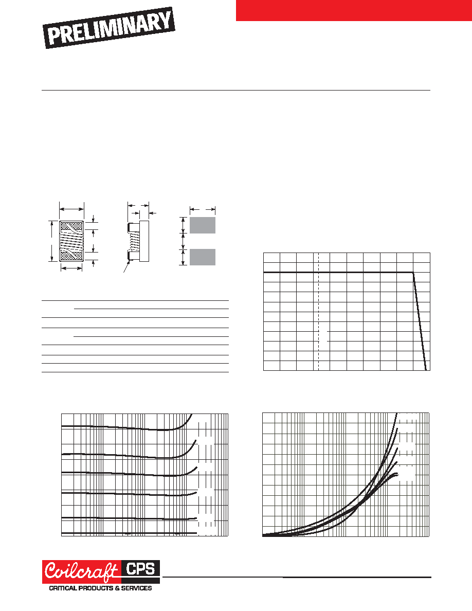
Typical L vs Frequency
Typical Q vs Frequency
Core material Ceramic
Terminations Silver-palladium-platinum-glass frit
Weight 0.7 – 1.0 mg
Ambient temperature –55°C to +140°C with
Irms current, +140°C
to +155°C with derated current
Storage temperature Component: –55°C to +155°C.
Packaging: –55°C to +80°C
Resistance to soldering heat Max three 40 second reflows at
+260°C, parts cooled to room temperature between cycles
Temperature Coefficient of Inductance (TCL) +25 to +125 ppm/°C
Moisture Sensitivity Level (MSL) 1 (unlimited floor life at <30°C /
85% relative humidity)
Enhanced Crush-Resitant Packaging 2000 per 7
″ reel.
Paper tape: 8 mm wide, 0.66 mm thick, 2 mm pocket spacing
Current Derating
Higher Q and lower DCR than other 0402 inductors
Very high SRF values – as high as 16 GHz
Excellent current handling capability – up to 2300 mA
52 inductance values from 1.0 to 220 nH
This robust version of Coilcraft’s standard 0402HP
series features high temperature materials that allow
operation in ambient temperatures up to 155°C.
-40
-20
0
20
40
60
80
100
160
140
120
Ambient temperature (°C)
P
e
rcent
of
rated
rmsI
120
110
100
90
80
70
60
50
40
30
20
10
0
25°C
A
B
overall
C
D
I
J
F
G
H
Suggested
Land Pattern
E
terminal
Terminal wraparound:
approx 0.007/0,18 both ends
DE
F
G
H
I
J
0.010
0.020
0.008
0.024
0.026
0.014
0.020
inches
0,25
0,51
0,20
0,61
0,66
0,36
0,51
mm
A max
B
C max
0.043
0.026 ±0.002
0.024
inches
1,09
0,66 ±0,051
0,61
mm
1–51 nH
A max
B
C max
0.044
0.026 ±0.002
0.026
inches
1,12
0,66 ±0,051
0,66
mm
56–220 nH
相關(guān)PDF資料 |
PDF描述 |
|---|---|
| ML235RAG15NJLH | 1 ELEMENT, 0.015 uH, CERAMIC-CORE, GENERAL PURPOSE INDUCTOR, SMD |
| ML312RAG3N3GLP | 1 ELEMENT, 0.0033 uH, CERAMIC-CORE, GENERAL PURPOSE INDUCTOR, SMD |
| ML312RAGR30GLC | 1 ELEMENT, 0.3 uH, CERAMIC-CORE, GENERAL PURPOSE INDUCTOR, SMD |
| ML312RAGR33JLC | 1 ELEMENT, 0.33 uH, CERAMIC-CORE, GENERAL PURPOSE INDUCTOR, SMD |
| ML312RAG68NGLP | 1 ELEMENT, 0.068 uH, CERAMIC-CORE, GENERAL PURPOSE INDUCTOR, SMD |
相關(guān)代理商/技術(shù)參數(shù) |
參數(shù)描述 |
|---|---|
| ML2375CCS | 制造商: 功能描述: 制造商:undefined 功能描述: |
| ML237B | 制造商:未知廠家 制造商全稱:未知廠家 功能描述:6 CHANNEL TOUCH CONTROL INTERFACE |
| ML-23D-10K | 制造商:TE Connectivity 功能描述: |
| ML-23D-5K | 制造商:TE Connectivity 功能描述: |
| ML23FAD | 制造商:MTRONPTI 制造商全稱:MTRONPTI 功能描述:Micropower CMOS Oscillators |
發(fā)布緊急采購,3分鐘左右您將得到回復(fù)。