- 您現(xiàn)在的位置:買賣IC網(wǎng) > PDF目錄377970 > ML4801CP (FAIRCHILD SEMICONDUCTOR CORP) Variable Feedforward PFC/PWM Controller Combo PDF資料下載
參數(shù)資料
| 型號: | ML4801CP |
| 廠商: | FAIRCHILD SEMICONDUCTOR CORP |
| 元件分類: | 穩(wěn)壓器 |
| 英文描述: | Variable Feedforward PFC/PWM Controller Combo |
| 中文描述: | 0.5 A POWER FACTOR CONTROLLER WITH POST REGULATOR, PDIP16 |
| 封裝: | PLASTIC, DIP-16 |
| 文件頁數(shù): | 8/14頁 |
| 文件大小: | 160K |
| 代理商: | ML4801CP |
ML4801
8
REV. 1.1 3/9/2001
Overvoltage Protection
boost voltage regulation loop.
Error Amplifier Compensation
cycle on its boost converter.
’
s
16.7kHz for a 100kHz switching frequency.
perturbations. However, the boost inductor will usually be
that of the voltage error amplifier.
information for the design of this class of PFC.
T
C
T
)
T
,
master oscillator:
(2)
following equation:
(3)
The ramp of the oscillator may be determined using:
(4)
FUNCTIONAL DESCRIPTION
(Continued)
15
15
VEAO
IEAO
IAC
-
-
+
+
16
16
2
2
4
4
3
3
VEA
-
-
+
+
IEA
+
+
-
-
GND
1
1
PFC
OUTPUT
GAIN
MODULATOR
Voltage and Current Error Amplifiers
The OVP comparator serves to protect the power circuit
from being subjected to excessive voltages if the load
should suddenly change. A resistor divider from the high
voltage DC output of the PFC is fed to V
FB
. When the
voltage on V
FB
exceeds 2.75V, the PFC output driver is
shut down. The PWM section will continue to operate. The
OVP comparator has 250mV of hysteresis, and the PFC
will not restart until the voltage at V
FB
drops below 2.5V.
The OVP trip level should be set at a level where the
active and passive external power components and the
ML4801 are within their safe operating voltages, but not
so low as to interfere with the regulator operation of the
The PWM loading of the PFC can be modeled as a
negative resistor; an increase in input voltage to the PWM
causes a decrease in the input current. This response
dictates the proper compensation of the two
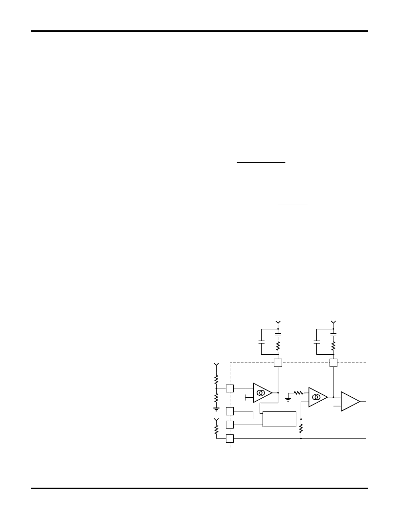
transconductance error amplifiers. Figure 2 shows the
types of compensation networks most commonly used for
the voltage and current error amplifiers, along with their
respective return points. The current loop compensation is
returned to V
REF
to produce a soft-start characteristic on
the PFC: as the reference voltage comes up from zero
volts, it creates a differentiated voltage on IEAO which
prevents the PFC from immediately demanding a full duty
There are two major concerns when compensating the
voltage loop error amplifier; stability and transient
response. Optimizing interaction between transient
response and stability requires that the error amplifier
’
s
open-loop crossover frequency should be 1/2 that of the
line frequency, or 23Hz for a 47Hz line (lowest
anticipated international power frequency). Rapid
perturbations in line or load conditions will cause the
input to the voltage error amplifier (V
FB
) to deviate from
its 2.5V (nominal) value. If this happens, the
transconductance of the voltage error amplifier will
increase significantly. This increases the gain-bandwidth
product of the voltage loop, resulting in a much more
rapid voltage loop response to such perturbations than
would occur with a conventional linear gain
characteristic. The current amplifier compensation is
similar to that of the voltage error amplifier with the
exception of the choice of crossover frequency. The
crossover frequency of the current amplifier should be at
least 10 times that of the voltage amplifier, to prevent
interaction with the voltage loop. It should also be limited
to less than 1/6th that of the switching frequency, e.g.
There is a also a degree of gain contouring applied to the
transfer characteristic of the current error amplifier, to
increase its speed of response to current-loop
the dominant factor in overall current loop response.
Therefore, this contouring is significantly less marked than
For more information on compensating the current and
voltage control loops, see Application Notes 33, 34, and
55. Application Note 16 also contains valuable
Oscillator (R
T
C
T
)
The oscillator frequency is set by the values of R
T
and C
T
,
which determine the ramp and off-time of the ML4801's
f
t
t
OSC
RAMP
DEADTIME
1
The deadtime of the oscillator is derived from the
t
C
R
V
V
RAMP
T
T
REF
REF
ln
.
.
125
375
at V
REF
= 7.5V:
t
C
R
RAMP
T
T
051
.
t
V
mA
C
C
DEADTIME
T
T
25
55
.
455
.
The deadtime is so small (t
RAMP
>> t
DEADTIME
) that the
VFB
VRMS
ISENSE
2.5V
VREF
Figure 2. Compensation Network Connections for the
相關(guān)PDF資料 |
PDF描述 |
|---|---|
| ML4801CS | Variable Feedforward PFC/PWM Controller Combo |
| ML4801IP | Variable Feedforward PFC/PWM Controller Combo |
| ML4801IS | Variable Feedforward PFC/PWM Controller Combo |
| ML4801 | Variable Feedforward PFC/PWM Controller Combo(前饋可變PFC/PWM控制器組合芯片) |
| ML4802CP | PFC/PWM Controller Combo with Green Mode |
相關(guān)代理商/技術(shù)參數(shù) |
參數(shù)描述 |
|---|---|
| ML4801CS | 功能描述:功率因數(shù)校正 IC SOIC-16 RoHS:否 制造商:Fairchild Semiconductor 開關(guān)頻率:300 KHz 最大功率耗散: 最大工作溫度:+ 125 C 安裝風(fēng)格:SMD/SMT 封裝 / 箱體:SOIC-8 封裝:Reel |
| ML4801CSX | 功能描述:功率因數(shù)校正 IC SOIC-16 RoHS:否 制造商:Fairchild Semiconductor 開關(guān)頻率:300 KHz 最大功率耗散: 最大工作溫度:+ 125 C 安裝風(fēng)格:SMD/SMT 封裝 / 箱體:SOIC-8 封裝:Reel |
| ML4801IP | 功能描述:功率因數(shù)校正 IC DIP-16 RoHS:否 制造商:Fairchild Semiconductor 開關(guān)頻率:300 KHz 最大功率耗散: 最大工作溫度:+ 125 C 安裝風(fēng)格:SMD/SMT 封裝 / 箱體:SOIC-8 封裝:Reel |
| ML4801IS | 功能描述:功率因數(shù)校正 IC SOIC-16 RoHS:否 制造商:Fairchild Semiconductor 開關(guān)頻率:300 KHz 最大功率耗散: 最大工作溫度:+ 125 C 安裝風(fēng)格:SMD/SMT 封裝 / 箱體:SOIC-8 封裝:Reel |
| ML4801ISX | 功能描述:功率因數(shù)校正 IC SOIC-16 RoHS:否 制造商:Fairchild Semiconductor 開關(guān)頻率:300 KHz 最大功率耗散: 最大工作溫度:+ 125 C 安裝風(fēng)格:SMD/SMT 封裝 / 箱體:SOIC-8 封裝:Reel |
發(fā)布緊急采購,3分鐘左右您將得到回復(fù)。