- 您現(xiàn)在的位置:買賣IC網(wǎng) > PDF目錄377972 > ML6509 (Fairchild Semiconductor Corporation) Active SCSI Terminator(SCSI系統(tǒng)的有源終端器) PDF資料下載
參數(shù)資料
| 型號: | ML6509 |
| 廠商: | Fairchild Semiconductor Corporation |
| 英文描述: | Active SCSI Terminator(SCSI系統(tǒng)的有源終端器) |
| 中文描述: | 活躍的SCSI終結(jié)者(的SCSI系統(tǒng)的有源終端器) |
| 文件頁數(shù): | 2/10頁 |
| 文件大?。?/td> | 121K |
| 代理商: | ML6509 |
ML6509
2
REV. 1.0 10/25/2000
GENERAL DESCRIPTION
(Continued)
One unique feature of the ML6509 is its support for a Low
Power mode, for use in Notebook and portable computer
applications, where it provides a 1mA (approximately
2.5K
termination) for less than 6" cable lengths. This
minimizes the battery drain significantly in such systems.
Current limiting and thermal shutdown protection are also
provided. The nine line configuration is optimal for wide
SCSI’s 18, 27, or 45 line termination needs.
NOTE :
The
DISCNKT
and
LPWR
lines have 200ky internal pullup resistors
connected to the supply. These pins should be left floating for normal
operation and should be connected to ground to enable the function.
PIN DESCRIPTION
NAME
DESCRIPTION
TERMPWR
Termination Power. Should be connected
to the SCSI TERMPWR line. A 10μF
tantalum local bypass capacitor is
recommended per system, as shown in
the application diagram
L1
Signal Termination 1. SCSI bus line 1
L2
Signal Termination 2. SCSI bus line 2
L3
Signal Termination 3. SCSI bus line 3
L4
Signal Termination 4. SCSI bus line 4
L5
Signal Termination 5. SCSI bus line 5
L6
Signal Termination 6. SCSI bus line 6
L7
Signal Termination 7. SCSI bus line 7
L8
Signal Termination 8. SCSI bus line 8
L9
Signal Termination 9. SCSI bus line 9
NAME
DESCRIPTION
V
REF
2.85V
REF
Output. External decoupling
with a 10μF tantalum in parallel with a
0.1μF ceramic capacitor is
recommended, as shown in the
application diagram.
DISCNKT
Disconnect Terminator. Logic input to
disconnect the terminator from the bus
when the SCSI device no longer needs
termination due to not being the last
device on the bus or otherwise. Active
low input.
LPWR
Low Power Mode. Logic input to switch
the terminator mode to a ~2.5k
termination, with a 1mA drive capability,
meant for power conscious battery
applications which use SCSI devices
supporting cable lengths less than six
inches. Active low input.
GND
HS
Ground. Signal Ground (0V)
Heat Sink Ground. Should be connected
to GND.
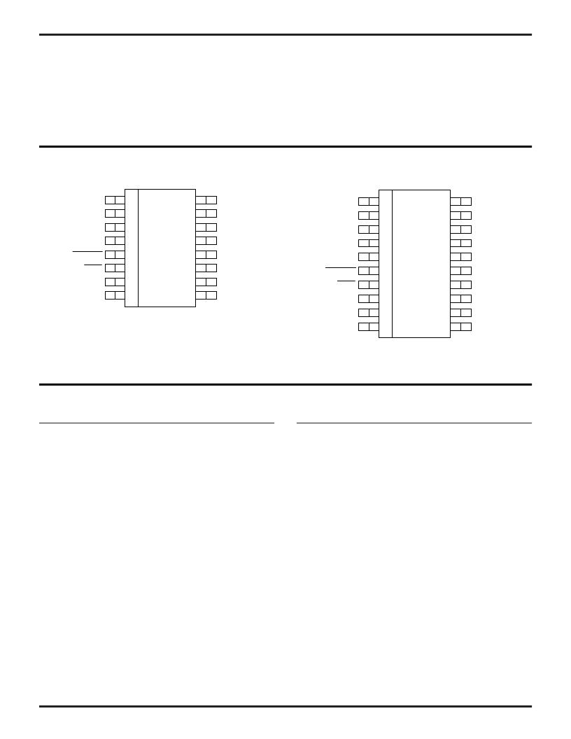
PIN CONFIGURATION
20-Pin TSSOP
16-Pin SOIC
TERMPWR
NC
NC
GND
DISCNKT
LPWR
L1
L2
L9
L8
L7
V
REF
L6
L5
L4
L3
1
2
3
4
5
6
7
8
16
15
14
13
12
11
10
9
TERMPWR
HS
NC
GND
NC
DISCNKT
LPWR
HS
L1
L2
L9
L8
HS
L7
V
REF
L6
L5
L4
HS
L3
1
2
3
4
5
6
7
8
9
10
20
19
18
17
16
15
14
13
12
11
相關(guān)PDF資料 |
PDF描述 |
|---|---|
| ML6510 | Series Programmable Adaptive Clock Manager(系列可編程自適應(yīng)時(shí)鐘管理器) |
| ML6516244 | 16-Bit Buffer/Line Driver with 3-State Outputs(BiCMOS 16位緩沖器/線驅(qū)動(dòng)器(三態(tài)輸出)) |
| ML6518 | 18 Line Hot-Insertable Active SCSI Terminator(線熱插入有源SCSI終端器) |
| ML65244 | High Speed Dual Quad Buffer/Line Drivers(高速雙通道四緩沖器/線驅(qū)動(dòng)器) |
| ML65L244 | High Speed Dual Quad Buffer/Line Drivers(高速雙通道四緩沖器/線驅(qū)動(dòng)器) |
相關(guān)代理商/技術(shù)參數(shù) |
參數(shù)描述 |
|---|---|
| ML6509 WAF | 制造商:Fairchild Semiconductor Corporation 功能描述: |
| ML6509CS | 制造商:Rochester Electronics LLC 功能描述:- Bulk |
| ML6509CS WAF UP | 制造商:Fairchild Semiconductor Corporation 功能描述: |
| ML6509CS UP WAF | 制造商:Fairchild Semiconductor Corporation 功能描述: |
| ML6509CT | 制造商:MICRO-LINEAR 制造商全稱:MICRO-LINEAR 功能描述:Active SCSI Terminator |
發(fā)布緊急采購,3分鐘左右您將得到回復(fù)。