- 您現(xiàn)在的位置:買賣IC網(wǎng) > PDF目錄377989 > MN2S1020 (Clare, Inc.) Mini-Dyad PDF資料下載
參數(shù)資料
| 型號: | MN2S1020 |
| 廠商: | Clare, Inc. |
| 英文描述: | Mini-Dyad |
| 中文描述: | 迷你二元 |
| 文件頁數(shù): | 3/5頁 |
| 文件大小: | 404K |
| 代理商: | MN2S1020 |
MN2
www.clare.com
Rev. 2
Mini-DYAD
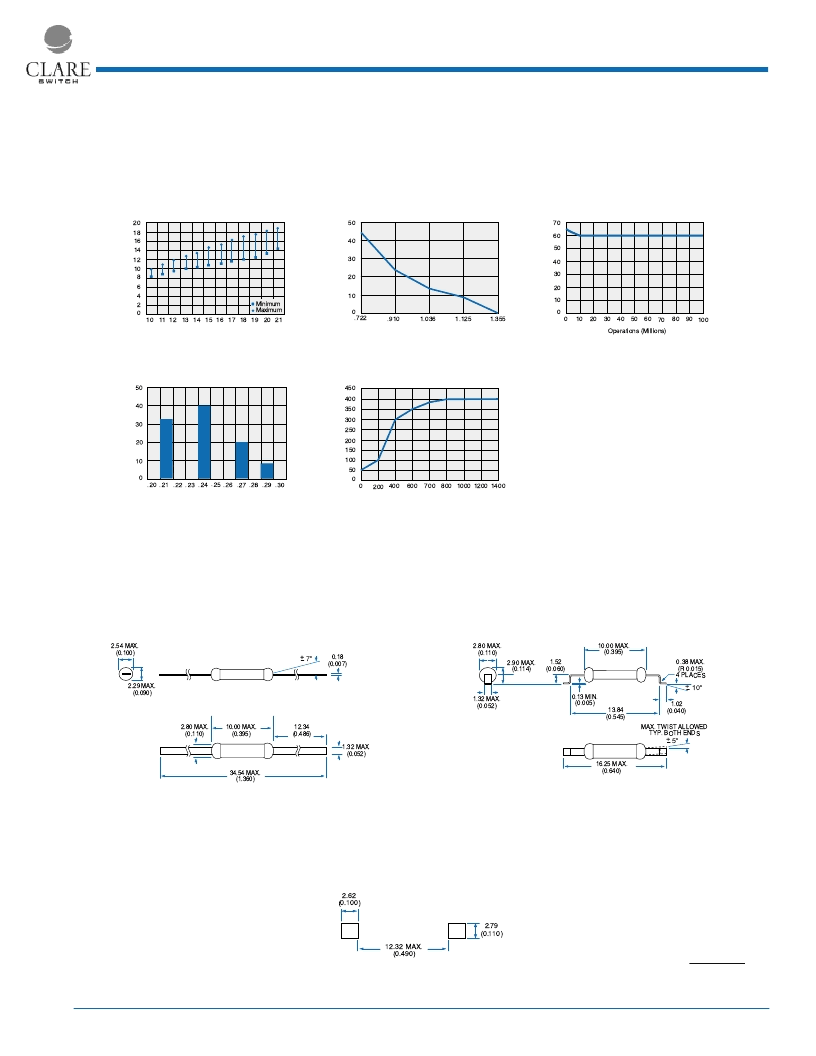
Performance Data*
*The Performance data shown in the graphs above is typical of device performance. For guaranteed parameters not indicated in the written specifications,
please contact our application department.
Recommended Pad Sizes
Mechanical Dimensions
Dimensions
mm
(inches)
Mini-Dyad
3
Mini-DYAD
Operate Shift After Lead Trim
Overall Length in Inches
P
50
40
30
20
10
0
.722
.910
1.036
1.125
1.355
Mini-DYAD
Test CoOperate NI vs. Release NI
20
Operate NI
R
10
12
10
8
18
16
14
6
4
2
0
11 12 13 14 15 16 17 18 19 20 21
Minimum
Maximum
Mini-DYAD
Capacitance Across Open Contacts
Capacitance (pF)
P
.20
30
20
50
40
10
0
.21 .22 .23 .24 .25 .26 .27 .28 .29 .30
TypicalMini-DYAD
10V, 10mA Resistive Load
Operations (Millions)
A
0
60
70
50
40
30
20
10
0
10
20
30
40
50
60
70
80
90 100
Mini-DYAD
Contact Resistance Throughout Life
50V, 100mA Resistive Load
Operations (Thousands)
A
0
300
350
400
450
250
200
150
100
50
0
200 400
600
700
800 1000 1200 1400
Mini-DYAD
34.54 MAX.
(1.360)
12.34
(0.486)
2.29 MAX.
(0.090)
2.54 MAX.
(0.100)
2.80 MAX.
(0.110)
1.32 MAX.
(0.052)
10.00 MAX.
(0.395)
0.18
(0.007)
+7
o
Mini-DYAD
SMT
13.84
(0.545)
1.02
(0.040)
0.38 MAX.
(R 0.015)
4 PLACES
16.25 MAX.
(0.640)
1.52
(0.060)
MAX. TWIST ALLOWED
TYP. BOTH ENDS
o
1.32 MAX.
(0.052)
2.90 MAX.
(0.114)
2.80 MAX.
(0.110)
10.00 MAX.
(0.395)
0.13 MIN.
(0.005)
+10
o
Mini Dyad
TM
SMT
12.32 MAX.
(0.490)
2.79
(0.110)
2.62
(0.100)
相關(guān)PDF資料 |
PDF描述 |
|---|---|
| MN2S1030 | Mini-Dyad |
| MN2S1520 | Mini-Dyad |
| MN2S1525 | Mini-Dyad |
| MN2S2025 | Mini-Dyad |
| MN2286 | Mini-Dyad |
相關(guān)代理商/技術(shù)參數(shù) |
參數(shù)描述 |
|---|---|
| MN2S1030 | 制造商:CLARE 制造商全稱:Clare, Inc. 功能描述:Mini-Dyad |
| MN2S1520 | 制造商:SRC Devices 功能描述: |
| MN2S1525 | 制造商:CLARE 制造商全稱:Clare, Inc. 功能描述:Mini-Dyad |
| MN2S2025 | 制造商:SRC Devices 功能描述: |
| MN2-S-32-430-1-2BB-B-C | 制造商:Carling Technologies 功能描述:M-SERIES CIRCUIT BREAKER - Bulk |
發(fā)布緊急采購,3分鐘左右您將得到回復(fù)。