- 您現(xiàn)在的位置:買賣IC網(wǎng) > PDF目錄377994 > MODEL 5B35 (Analog Devices, Inc.) Linearized 4-Wire RTD Input Module(線性化四線RTD輸入模塊) PDF資料下載
參數(shù)資料
| 型號(hào): | MODEL 5B35 |
| 廠商: | Analog Devices, Inc. |
| 英文描述: | Linearized 4-Wire RTD Input Module(線性化四線RTD輸入模塊) |
| 中文描述: | 線性化的4線RTD輸入模塊(線性化四線電阻輸入模塊) |
| 文件頁(yè)數(shù): | 1/2頁(yè) |
| 文件大小: | 52K |
| 代理商: | MODEL 5B35 |
REV. 0
Information furnished by Analog Devices is believed to be accurate and
reliable. However, no responsibility is assumed by Analog Devices for its
use, nor for any infringements of patents or other rights of third parties
which may result from its use. No license is granted by implication or
otherwise under any patent or patent rights of Analog Devices.
a
MODEL 5B35
One Technology Way, P.O. Box 9106, Norwood, MA 02062-9106, U.S.A.
Tel: 781/329-4700
World Wide Web Site: http://www.analog.com
Fax: 781/326-8703
Analog Devices, Inc., 1997
Linearized 4-Wre RTD
Input Module
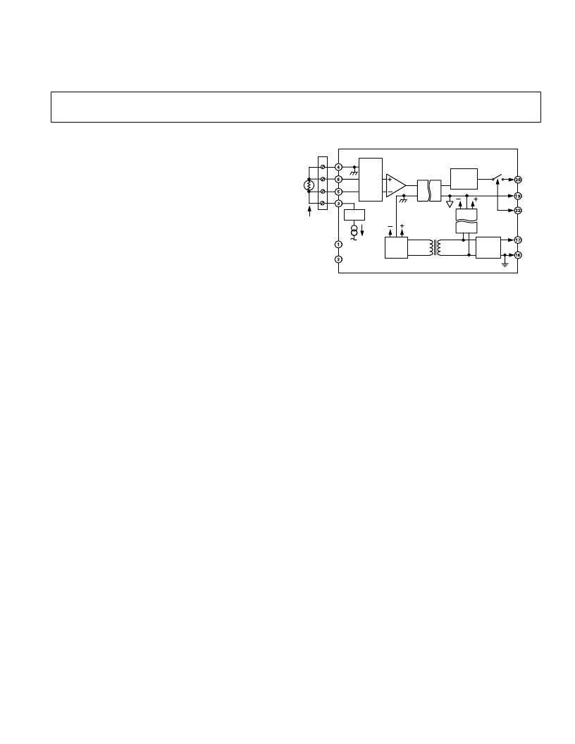
FUNCT IONAL BLOCK DIAGRAM
GE NE RAL DE SCRIPT ION
Model 5B35 converts the input from a wide variety of RT D
types to a linearized, high accuracy output of 0 V to +5 V. T he
module provides transformer isolation, RT D excitation, RT D
lead-resistance compensation, signal filtering and input protec-
tion against line voltage connection. A series output switch
eliminates the need for external multiplexing. T he industry
standard 5B Series encapsulated plug-in modular package is
compatible with all 5B backplanes. Modules are powered by
+5 V dc,
±
5%.
Signal isolation is provided by transformer coupling using a
proprietary technique for linear, stable performance. A demodu-
lator on the output side of the signal transformer recovers the
input signal, which is filtered and buffered to provide an accu-
rate, low impedance, low noise output.
T rue three-port isolation includes common-mode voltage of:
1500 V rms between input and output, and between input and
power; 250 V rms between output and power.
T he modules provide RT D excitation from a precision current
source. A low drift, chopper stabilized, differential amplifier
design allows for the use of very low RT D excitation currents to
minimize accuracy losses from self-heating of the RT D. T he low
input offset drift of
±
0.01
°
C/
°
C and gain drift of
±
30 ppm/
°
C
assure that accuracy is maintained over a wide operating tem-
perature range.
FEATURES
Accepts a Variety of RTD Types
100
V
Platinum, 10
V
Copper, 120
V
Nickel
Linearizes RTD Signal
1500 V rms Input/Output and Input/Power Isolation
250 V rms Output/Power Isolation
240 V rms Field Wiring Protection
4-Wire Lead Resistance Compensation
190 dB CMRR
116 dB NMR @ 60 Hz, 108 dB @ 50 Hz
Low Drift:
Input Offset
6
0.01
8
C/
8
C
Gain
6
30 ppm/
8
C
Low Output Noise:
0.3 mV p-p @ 100 kHz BW
6 mV p-p @ 5 MHz BW
Low Power Consumption: +5 V dc @ 15 mA
ANSI/IEEE C37.90.1–1989 Transient Protection
CSA, FM and CE Approvals
T he four-wire configuration of the 5B35 supplies the RT D
excitation current through two leads that are not the signal input
leads. Because there is no excitation current in the signal input
leads, the lead lengths or resistances have no effect on the RT D
measurement.
An optimized five-pole Butterworth filter (with 4 Hz bandwidth)
provides 116 dB of normal-mode rejection at 60 Hz and 108dB
at 50 Hz. Output noise is an exceptionally low 0.3 mV p-p at
100 kHz bandwidth and 6 mV p-p at 5 MHz bandwidth.
T he input circuit is protected against accidental application of
voltages, such as an ac power line, up to 240 V rms continuous.
A series output switch is included to eliminate the need for
external multiplexing in many applications. T his switch has a
low output resistance and is controlled by an active-low enable
input. When the output switch is not used, ground the enable
input to I/O common to turn on the switch.
SIGNAL
ISOLATION
CHOPPER
DIF AMP
4-POLE
ACTIVE
LPF
P.S.
POWER
ISOLATION
RECT.
AND
FILTER
POWER
OSC.
V
OUT
I/O
COM
READ
EN (0)
+5V
PWR
COM
4
3
2
1
PROT
4-WIRE
RTD
5B
BACKPLANE
5B35
NC
NC
NC = NO CONNECT
PROT.
&
FILTER
相關(guān)PDF資料 |
PDF描述 |
|---|---|
| MODEL 5B36 | Potentiometer RTD Input Module(電位測(cè)試功能的RTD輸入模塊) |
| MODEL 5B42 | Process Current Input Module(電流輸入轉(zhuǎn)換處理模塊) |
| Model | Ultracompact Precision10 V/5 V/2.5 V/3.0 V Voltage References |
| MP1230A | CMOS Microprocessor Compatible Double-Buffered 12-Bit Digital-to-Analog Converter |
| MP1230ABN | CMOS Microprocessor Compatible Double-Buffered 12-Bit Digital-to-Analog Converter |
相關(guān)代理商/技術(shù)參數(shù) |
參數(shù)描述 |
|---|---|
| MODEL601-1045 | 制造商:VISHAY 制造商全稱:Vishay Siliconix 功能描述:Full 360° Smart Position Sensor |
| MODEL657 | 制造商:VISHAY 制造商全稱:Vishay Siliconix 功能描述:Industrial Rotary Position Sensor Bushing Mount Type, Conductive Plastic |
| MODEL700 | 制造商:未知廠家 制造商全稱:未知廠家 功能描述:Load cells - tension and compression |
| MODEL702 | 制造商:VISHAY 制造商全稱:Vishay Siliconix 功能描述:7/8 (22.2 mm) Single Turn Wirewound Precision Potentiometer |
| MODEL708 | 制造商:VISHAY 制造商全稱:Vishay Siliconix 功能描述:7/8inch (22.2 mm) Single Turn Conductive Plastic Precision Potentiometer |
發(fā)布緊急采購(gòu),3分鐘左右您將得到回復(fù)。