- 您現(xiàn)在的位置:買賣IC網(wǎng) > PDF目錄201947 > MOR283R3DZ (CRANE ELECTRONICS INC) 2-OUTPUT 66 W DC-DC REG PWR SUPPLY MODULE PDF資料下載
參數(shù)資料
| 型號: | MOR283R3DZ |
| 廠商: | CRANE ELECTRONICS INC |
| 元件分類: | 電源模塊 |
| 英文描述: | 2-OUTPUT 66 W DC-DC REG PWR SUPPLY MODULE |
| 封裝: | MODULE-12 |
| 文件頁數(shù): | 18/24頁 |
| 文件大?。?/td> | 2126K |
| 代理商: | MOR283R3DZ |
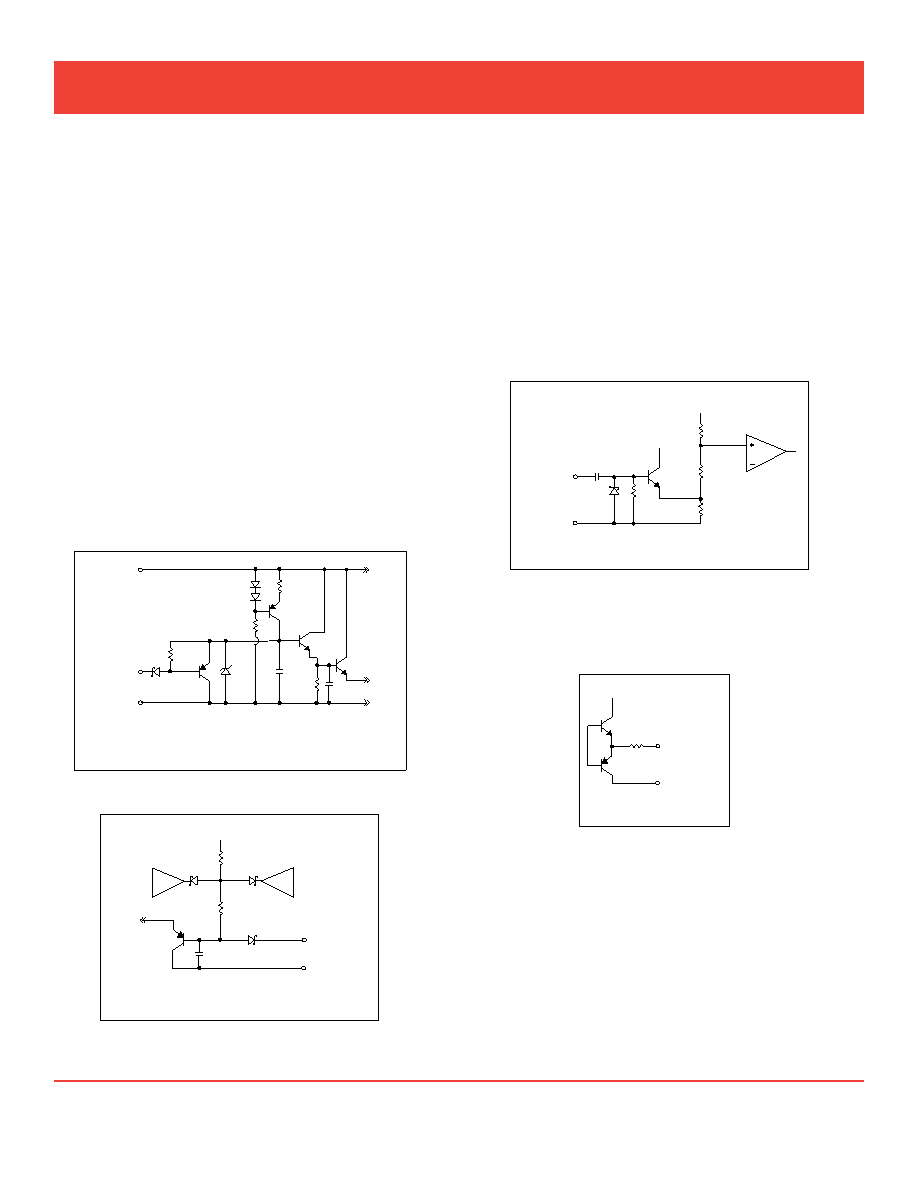
inhibit 1 and 2
Two inhibit terminals disable switching, resulting in no output
and very low quiescent input current. The two inhibit pins allow
access to an inhibit function on either side of the isolation barrier
to help maintain isolation.
An open collector is required for interfacing with both of the
inhibit pins. Applying an active low to either inhibit pin will inhibit
the converter. Leaving the pins open will enable the converter.
Inhibit 1 is referenced to Input Common. Inhibit 2 is refer-
enced to Sense Return for single output models and to Output
Common for dual output models.
The open circuit voltage (unit enabled) for Inhibit 1 is 13 V
and for Inhibit 2 it is up to 8 V. Leave the Inhibit pins uncon-
nected if not used. The required active low voltage level is 0.8
V maximum for Inhibit 1 and 0.2 V maximum for Inhibit 2. See
Figures 4 and 5.
underVoltage loCkout
Undervoltage lockout prevents the units from operating below
approximately 15.5 VDC input voltage to keep system current
levels smooth, especially during initialization or re-start opera-
tions.
SynC in and SynC out
The MOR converters can be synchronized to the system clock
by applying an active high sync signal to the Sync In pin. Sync
Out can be used to synchronize other components to the MOR
converter’s switching frequency.
The frequency range for external synchronization is 525 to 625
kHz. The requirements for an external signal are 15% to 50%
dutycycle,0≤L≤0.8Vand4.5≤H≤9V.BothSyncInand
Sync Out are referenced to input common. Sync In should be
connected to input common if not used. See Figures 6 and 7.
PoSitiVe outPut, negatiVe outPut and
outPut Common
Output current is typically limited to 125% of maximum specified
current under short circuit or load fault conditions.
Single output models operate from no load to full load. Dual
output models with balanced loads operate from no load to full
load. For dual models with unbalanced loads, at least 10% of
the total output power must be drawn from the positive output
at all times, however, the negative output does not require a
minimum load. See note 4, cross regulation, under the Electrical
Characteristics Tables.
~~
Sync In
Input
Common
5V
V
CC
330 pF
1.8 k
10 k
1 k
Figure 6: SynC in
~~
Sync Out
Input
Common
V
CC
200
Figure 7: SynC out
V
CC
Positive
Input
Inhibit 1
Input
Common
MOR Input Side
10 k
20 k
12V
200
Figure 4: inhibit 1
V
S
~~
Current
Limit
Feedback
Voltage
E/A
Inhibit 2
Sense
Return
MOR Output Side - Single Output
200
10 k
Figure 5: inhibit 2
Crane Aerospace & Electronics Power Solutions
Mor single and dual dc/dc converters
28 Volt input – 120 Watt
www.interpoint.com
Page 3 of 24
MOR Rev K - 20100422
相關(guān)PDF資料 |
PDF描述 |
|---|---|
| MAX6728AKAWED2-T | 1-CHANNEL POWER SUPPLY MANAGEMENT CKT, PDSO8 |
| MAX6728AKAZGD1-T | 1-CHANNEL POWER SUPPLY MANAGEMENT CKT, PDSO8 |
| MAX6728AKAZGD6-T | 1-CHANNEL POWER SUPPLY MANAGEMENT CKT, PDSO8 |
| MAX6733AUTMRD6-T | 1-CHANNEL POWER SUPPLY MANAGEMENT CKT, PDSO6 |
| MAX6733AUTWED5-T | 1-CHANNEL POWER SUPPLY MANAGEMENT CKT, PDSO6 |
相關(guān)代理商/技術(shù)參數(shù) |
參數(shù)描述 |
|---|---|
| MOR283R3DZ/883 | 制造商:CRANE 制造商全稱:CRANE 功能描述:MOR Single and Dual DC/DC Converters |
| MOR283R3DZ/ES | 制造商:CRANE 制造商全稱:CRANE 功能描述:MOR Single and Dual DC/DC Converters |
| MOR283R3S | 制造商:INTERPOINT 制造商全稱:INTERPOINT 功能描述:Parallel operation with current share, up to 5 units (540 watts) |
| MOR283R3S/883 | 制造商:CRANE 制造商全稱:CRANE 功能描述:MOR Single and Dual DC/DC Converters |
| MOR283R3S/ES | 制造商:CRANE 制造商全稱:CRANE 功能描述:MOR Single and Dual DC/DC Converters |
發(fā)布緊急采購,3分鐘左右您將得到回復(fù)。