- 您現(xiàn)在的位置:買賣IC網(wǎng) > PDF目錄377996 > MP7543AD (EXAR CORP) 5 V CMOS Serial Input 12-Bit Digital-to-Analog Converter PDF資料下載
參數(shù)資料
| 型號: | MP7543AD |
| 廠商: | EXAR CORP |
| 元件分類: | DAC |
| 英文描述: | 5 V CMOS Serial Input 12-Bit Digital-to-Analog Converter |
| 中文描述: | SERIAL INPUT LOADING, 12-BIT DAC, CDIP16 |
| 封裝: | 0.300 INCH, CERAMIC, DIP-16 |
| 文件頁數(shù): | 5/12頁 |
| 文件大小: | 128K |
| 代理商: | MP7543AD |
MP7543
5
Rev. 2.00
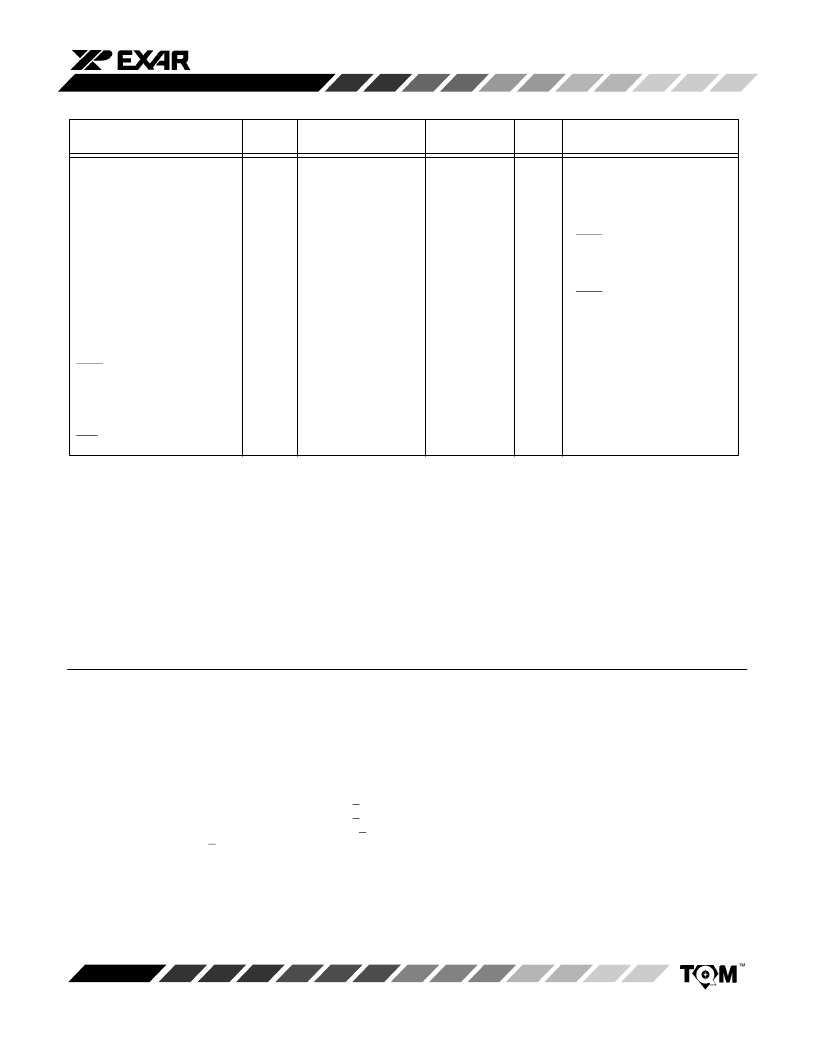
ELECTRICAL CHARACTERISTICS (CONT’D)
25
°
C
Typ
Tmin to Tmax
Min
NOTES:
Specifications are subject to change without notice
1
2
3
4
Full Scale Range (FSR) is 10V for unipolar mode.
Guaranteed but not production tested.
Digital input levels should not go below ground or exceed the positive supply voltage, otherwise damage may occur.
See timing diagram.
Parameter
Symbol
Min
Max
Max
Units
Test Conditions/Comments
SWITCHING
CHARACTERISTICS
2, 4
Serial Input to Strobe Set-up Time
Serial Input to Strobe Set-up Time
Serial Input to Strobe Set-up Time
Serial Input to Strobe Set-up Time
Serial Input to Strobe Hold Time
Serial Input to Strobe Hold Time
Serial Input to Strobe Hold Time
Serial Input to Strobe Hold Time
SRI Data Pulse Width
STB1 Pulse Width
STB4 Pulse Width
STB3 Pulse Width
STB2 Pulse Width
Load Pulse Width
Minimum time between strobing
Reg. A and loading Reg. B
CLR pulse width
t
DS1
t
DS4
t
DS3
t
DS2
t
DH1
t
DH4
t
DH3
t
DH2
t
SRI
t
STB1
t
STB4
t
STB3
t
STB2
t
LD1, 2
t
ASB
50
0
0
20
30
80
80
60
80
80
100
100
80
150
100
ns
ns
ns
ns
ns
ns
ns
ns
ns
ns
ns
ns
ns
ns
ns
STB1 used as a strobe
STB4 used as a strobe
STB3 used as a strobe
STB2 used as a strobe
STB1 used as a strobe
STB4 used as a strobe
STB3 used as a strobe
STB2 used as a strobe
0
0
40
60
160
160
120
160
160
200
200
160
300
0
0
t
CLR
200
400
ns
ABSOLUTE MAXIMUM RATINGS (T
A
= +25
°
C unless otherwise noted)
1, 2, 3
V
DD
to GND
Digital Input Voltage to GND (2)
I
OUT1
, I
OUT2
to GND
V
REF
to GND (2)
V
RFB
to GND (2)
AGND to DGND
(Functionality Guaranteed +0.5 V)
+7 V
. . . . . . . . . . . . . . . . . . . . . . . . . . . . . . . . . . . .
.
. . . . . . . . . . .
. . . . . . . . . . . . . . . . . . . . . . . . . . . . . . .
. . . . . . . . . . . . . . . . . . . . . . . . . . . . . . .
. . . . . . . . . . . . . . . . . . . . . . . . . . . . . . . . .
GND –0.5 to V
DD
+0.5 V
GND –0.5 to V
DD
+0.5 V
+25 V
+25 V
+1 V
Storage Temperature
–65
°
C to +150
°
C
. . . . . . . . . . . . . . . . .
Lead Temperature (Soldering, 10 seconds)
+300
°
C
. . . . . .
Package Power Dissipation Rating to 75
°
C
CDIP, PDIP, SOIC, PLCC
Derates above 75
°
C
700mW
10mW/
°
C
. . . . . . . . . . . . . . . . . .
. . . . . . . . . . . . . . . . . . . . .
NOTES:
1
Stresses above those listed under “Absolute Maximum Ratings” may cause permanent damage to the device. This is a
stress rating only and functional operation at or above this specification is not implied. Exposure to maximum rating
conditions for extended periods may affect device reliability.
Any input pin which can see a value outside the absolute maximum ratings
should be protected by Schottky diode clamps
(HP5082-2835) from input pin to the supplies. All inputs have protection diodeswhich will protect the device from short
transients outside the supplies of less than 100mA for less than 100
μ
s.
GND refers to AGND and DGND.
2
3
相關(guān)PDF資料 |
PDF描述 |
|---|---|
| MP7543BD | 5 V CMOS Serial Input 12-Bit Digital-to-Analog Converter |
| MP7543JS | 5 V CMOS Serial Input 12-Bit Digital-to-Analog Converter |
| MP7543KN | 5 V CMOS Serial Input 12-Bit Digital-to-Analog Converter |
| MP7543KP | 5 V CMOS Serial Input 12-Bit Digital-to-Analog Converter |
| MP7543KS | 5 V CMOS Serial Input 12-Bit Digital-to-Analog Converter |
相關(guān)代理商/技術(shù)參數(shù) |
參數(shù)描述 |
|---|---|
| MP7543BD | 制造商:EXAR 制造商全稱:EXAR 功能描述:5 V CMOS Serial Input 12-Bit Digital-to-Analog Converter |
| MP7543JN | 制造商:EXAR 制造商全稱:EXAR 功能描述:5 V CMOS Serial Input 12-Bit Digital-to-Analog Converter |
| MP7543JP | 制造商:EXAR 制造商全稱:EXAR 功能描述:5 V CMOS Serial Input 12-Bit Digital-to-Analog Converter |
| MP7543JS | 制造商:EXAR 制造商全稱:EXAR 功能描述:5 V CMOS Serial Input 12-Bit Digital-to-Analog Converter |
| MP7543KN | 制造商:EXAR 制造商全稱:EXAR 功能描述:5 V CMOS Serial Input 12-Bit Digital-to-Analog Converter |
發(fā)布緊急采購,3分鐘左右您將得到回復(fù)。