- 您現(xiàn)在的位置:買賣IC網(wǎng) > PDF目錄377996 > MP7610CP (EXAR CORP) D/A Converter with Output Amplifier and Serial Data/Address mP Control Logic PDF資料下載
參數(shù)資料
| 型號: | MP7610CP |
| 廠商: | EXAR CORP |
| 元件分類: | DAC |
| 英文描述: | D/A Converter with Output Amplifier and Serial Data/Address mP Control Logic |
| 中文描述: | OCTAL, SERIAL INPUT LOADING, 30 us SETTLING TIME, 14-BIT DAC, PQCC44 |
| 封裝: | PLASTIC, LCC-44 |
| 文件頁數(shù): | 6/16頁 |
| 文件大小: | 571K |
| 代理商: | MP7610CP |
MP7610
6
Rev. 4.01
25
°
C
Typ
Tmin to Tmax
Min
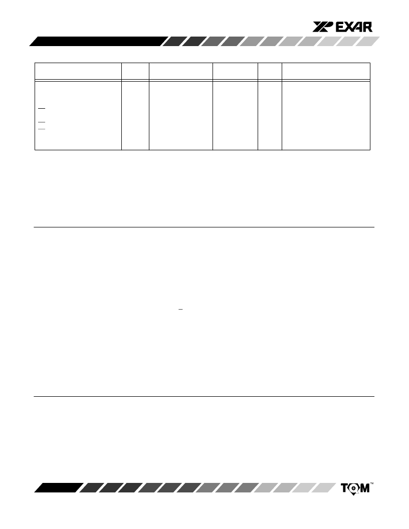
ELECTRICAL CHARACTERISTICS (CONT’D)
Specifications aresubjectto change withoutnotice
Parameter
Symbol
Min
Max
Max
Units
Test Conditions/Comments
DIGITAL TIMING
SPECIFICATIONS
1, 4
(CONT’D
)
LD Rising Edge to SDO
Tri-state Disable
LD Rising Edge to CLK Enable
LD Set-up Time with Respect
to CLK
t
HZ2
50
ns
t
LDCK
t
LDSU
50
45
ns
ns
NOTES:
1
2
3
4
5
6
Guaranteed; not tested.
Specified values guarantee functionality.
Digital inputs should not go below digital GND or exceed DV
DD
supply voltage.
See Figures 2 and 3. All digital input signals are specified with t
R
= t
F
= 10 ns 10% to 90% and timed from a 50% voltage level.
For powersupply values <
|
2
£
V
REF
, the outputswing is limited as specified in Analog Outputs.
Digital feedthrough and channel-to-channel crosstalk are heavily dependenton the board layout and environment.
ABSOLUTE MAXIMUM RATINGS (TA = +25
°
C unless otherwise noted)
1, 2
V
CC
to AGND
V
EE
to AGND
DV
DD
to DGND
V
REF
to DGND
AGND to DGND
(Functionality guaranteed for
|
0.5 V only)
+16.5 V
. . . . . . . . . . . . . . . . . . . . . . . . . . .
--16.5 V
. . . . . . . . . . . . . . . . . . . . . . . . . . .
+6.5 V
. . . . . . . . . . . . . . . . . . . . . . . . . .
+7.0 V
. . . . . . . . . . . . . . . . . . . . . . . . . . .
+1 V
. . . . . . . . . . . . . . . . . . . . . . . . . . . .
Digital Input & Output Voltage
to DGND
. . . . . . . . . . . . . . . . . . . .
--0.5 to DV
DD
+0.5V
Analog Inputs & Outputs
V
CC
, V
EE
, DV
DD
, AGND, DGND (provided that power
dissipation of the package spec is not exceeded)
Operating Temperature Range
Extended Industrial
. . . . . . . . . . . . . .
Maximum J unction Temperature
Storage Temperature
. . . . . . . . . . . . . . . . . . . . . .
Lead Temperature (Soldering, 10 sec)
Package Power Dissipation Rating @ 75
°
C
SOIC, PLCC
. . . . . . . . . . . . . . . . . . . . . . . . . . .
Derates above 75
°
C
. . . . . . . . . . . . . . . . . . . .
Indefinite Shorts to
. . . . . . .
--40
°
C to +85
°
C
--65
°
C to 150
°
C
. . .
150
°
C
+300
°
C
. . . . .
1150mW
15mW/
°
C
NOTES:
1
Stresses above those listed under “Absolute MaximumRatings” may cause permanent damage to the device. This is a
stress rating only and functional operation at or above this specification is not implied. Exposure to maximum rating
conditions for extended periods may affect device reliability.
Any input pin which can see a value outside the absolute maximumratings should be protected by Schottky diode clamps
(HP5082-2835) from input pin to the supplies. All inputs have protection diodes which will protect the device fromshort
transients outside the supplies of less than 100mA for less than 100
μ
s.
2
APPLICATION NOTES
NOTE: When using these DACs to drive remote devices, the accuracy of the outputcan be improved by utilizing a remote analog
groundconnection. The differencebetweentheDGND andAGNDshouldbelimitedto
|
300mV toassurenormaloperation. Ifthere
is any chance thatthe AGND toDGND canbe greaterthan
|
1 V, we recommendtwoback-to-backdiodes be usedbetweenDGND
andAGND toclampthevoltageandpreventdamagetotheDAC. Using a bufferbetweentheremotegroundlocationandAGND may
help reduce noise induced from long lead or trace lengths.
相關(guān)PDF資料 |
PDF描述 |
|---|---|
| MP7610CS | D/A Converter with Output Amplifier and Serial Data/Address mP Control Logic |
| MP7611 | Octal 14-Bit DAC Array D/A Converter with Output Amplifier and Parallel Data/Address UP Control Logic |
| MP7611AE | Octal 14-Bit DAC Array D/A Converter with Output Amplifier and Parallel Data/Address UP Control Logic |
| MP7611AP | Octal 14-Bit DAC Array D/A Converter with Output Amplifier and Parallel Data/Address UP Control Logic |
| MP7611BE | Octal 14-Bit DAC Array D/A Converter with Output Amplifier and Parallel Data/Address UP Control Logic |
相關(guān)代理商/技術(shù)參數(shù) |
參數(shù)描述 |
|---|---|
| MP7610CS | 制造商:EXAR 制造商全稱:EXAR 功能描述:D/A Converter with Output Amplifier and Serial Data/Address mP Control Logic |
| MP7611 | 制造商:EXAR 制造商全稱:EXAR 功能描述:Octal 14-Bit DAC Array D/A Converter with Output Amplifier and Parallel Data/Address UP Control Logic |
| MP7611AE | 制造商:EXAR 制造商全稱:EXAR 功能描述:Octal 14-Bit DAC Array D/A Converter with Output Amplifier and Parallel Data/Address UP Control Logic |
| MP7611AP | 制造商:EXAR CORP 功能描述: |
| MP7611BE | 制造商:EXAR 制造商全稱:EXAR 功能描述:Octal 14-Bit DAC Array D/A Converter with Output Amplifier and Parallel Data/Address UP Control Logic |
發(fā)布緊急采購,3分鐘左右您將得到回復。