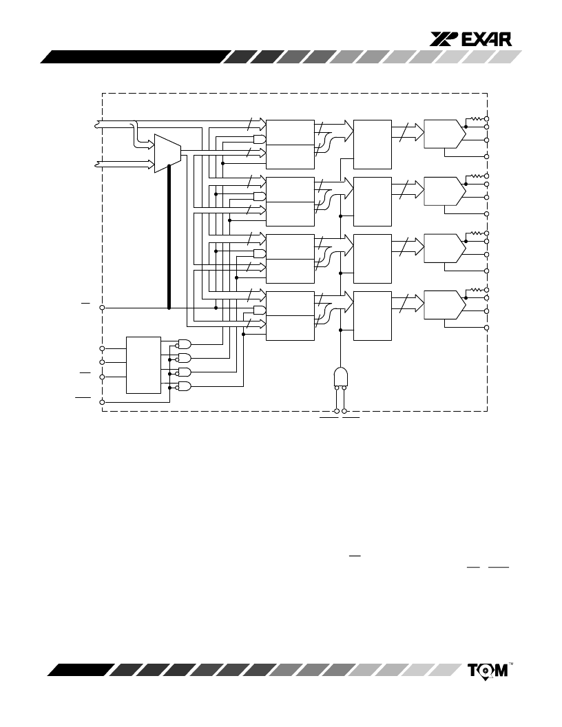
- 您現(xiàn)在的位置:買賣IC網(wǎng) > PDF目錄377997 > MP7680JN (MICRO POWER SYSTEMS) 5 V CMOS 12-Bit Quad Double-Buffered Multiplying Digital-to-Analog Converter PDF資料下載
參數(shù)資料
| 型號(hào): | MP7680JN |
| 廠商: | MICRO POWER SYSTEMS |
| 元件分類: | DAC |
| 英文描述: | 5 V CMOS 12-Bit Quad Double-Buffered Multiplying Digital-to-Analog Converter |
| 中文描述: | PARALLEL, WORD INPUT LOADING, 1 us SETTLING TIME, 12-BIT DAC, PDIP40 |
| 文件頁數(shù): | 8/12頁 |
| 文件大小: | 307K |
| 代理商: | MP7680JN |

MP7680
8
Rev. 3.10
MUX
1
0
DAC
B1
Latch
B2
Latch
D
E
Q
D
E
Q
D
E
Q
12
4
8
8
4
12
4
8
8
4
DAC
B1
Latch
B2
Latch
D
E
Q
D
E
Q
D
E
Q
12
4
8
8
4
DAC
B1
Latch
B2
Latch
D
E
Q
D
E
Q
D
E
Q
12
4
8
8
4
DAC
B1
Latch
B2
Latch
D
E
Q
D
E
Q
D
E
Q
Latch
Address
Decoder
DA11 - DA0
LA11 - LA0
DAC LA TCHES
INPUT
LA TCHES
DB11-DB4
(MSB)
DB3-DB0
(LSB)
B1/B2
A1 (MSB)
A0 (LSB)
CS
WR1
WR2
XFER
DB11-
DB8
Enable A
Enable B
Enable C
Enable D
DB11 - DB0
DC11 - DC0
DD11 - DD0
Transfer
Disable-B1
R
FBA
I
OUT1A
I
OUT2A
R
FBB
I
OUT1B
I
OUT2B
R
FBC
I
OUT1C
I
OUT2C
R
FBD
I
OUT1D
I
OUT2D
V
REFA
V
REFB
V
REFC
V
REFD
Figure
3.
Latches
Control
Logic
THEOR Y OF OPERA TION
Digital
Interface
Figure
controls the writing of the input latches and the one that
controls the DAC latches are completely separated. It is
easy to understand how the MP7680/80A works by
understanding each basic operation.
3.
shows the internal control logic. The logic that
W riting
to Input
Latches
BykeepingB1/B2=high,a12-bitbushasdirectaccessto
the12bitsoftheinputlatches. TheconditionCS= WR1=
0 loads the values contained in the data bus DB11-DB0
into the input latch addresses by A
1
, A
0
(
Figure
Table 1.
).
4.
,
相關(guān)PDF資料 |
PDF描述 |
|---|---|
| MP7680KE | 5 V CMOS 12-Bit Quad Double-Buffered Multiplying Digital-to-Analog Converter |
| MP7680KN | 5 V CMOS 12-Bit Quad Double-Buffered Multiplying Digital-to-Analog Converter |
| MP7682SD | CMOS, 6-Bit High-Speed Analog-to-digital Converter |
| MP7682 | CMOS, 6-Bit High-Speed Analog-to-digital Converter |
| MP7682JN | CMOS, 6-Bit High-Speed Analog-to-digital Converter |
相關(guān)代理商/技術(shù)參數(shù) |
參數(shù)描述 |
|---|---|
| MP7680KE | 制造商:EXAR 制造商全稱:EXAR 功能描述:5 V CMOS 12-Bit Quad Double-Buffered Multiplying Digital-to-Analog Converter |
| MP7680KN | 制造商:EXAR 制造商全稱:EXAR 功能描述:5 V CMOS 12-Bit Quad Double-Buffered Multiplying Digital-to-Analog Converter |
| MP7682 | 制造商:EXAR 制造商全稱:EXAR 功能描述:CMOS, 6-Bit High-Speed Analog-to-digital Converter |
| MP7682JN | 制造商:EXAR 制造商全稱:EXAR 功能描述:CMOS, 6-Bit High-Speed Analog-to-digital Converter |
| MP7682JS | 制造商:Micro Power Systems Inc 功能描述:6-BIT FLASH METHOD ADC, PARALLEL ACCESS, PDSO18 |
發(fā)布緊急采購,3分鐘左右您將得到回復(fù)。