- 您現(xiàn)在的位置:買賣IC網(wǎng) > PDF目錄299520 > MS416PJB683MSH (COILCRAFT INC) 1 ELEMENT, 68 uH, FERRITE-CORE, GENERAL PURPOSE INDUCTOR, SMD PDF資料下載
參數(shù)資料
| 型號(hào): | MS416PJB683MSH |
| 廠商: | COILCRAFT INC |
| 元件分類: | 通用定值電感 |
| 英文描述: | 1 ELEMENT, 68 uH, FERRITE-CORE, GENERAL PURPOSE INDUCTOR, SMD |
| 文件頁(yè)數(shù): | 1/2頁(yè) |
| 文件大?。?/td> | 223K |
| 代理商: | MS416PJB683MSH |
1102 Silver Lake Road
Cary IL 60013
Phone
Fax
800-981-0363
847-639-1508
E-mail
Web
cps@coilcraft.com
www.coilcraft-cps.com
Coilcraft, Inc. 2011
These parts are preproduction products for electrical evaluation only.
Specification subject to change without notice.
Document MS433-1 Revised 03/25/11
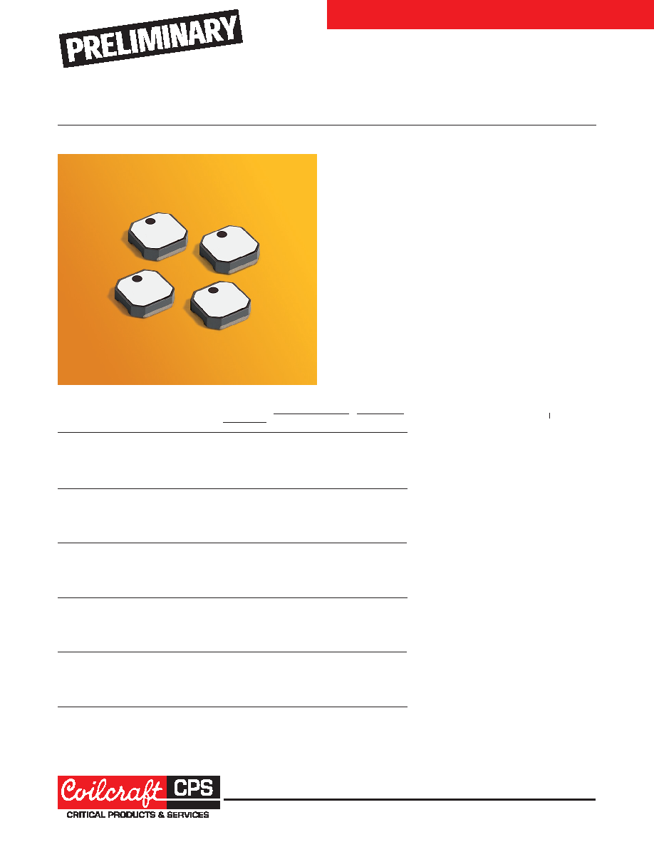
High-Reliability Power Inductors MS416PJB
4012 POWER INDUCTORS
■
High temperature materials allow operation in ambient
temperatures up to 155°C.
■
Special construction allows it to pass vibration testing to
80 G and shock testing to 1000 G.
■
Tin-lead (Sn-Pb) termination for the best possible board
adhesion
Core material Ferrite
Terminations Tin-lead (63/37) over tin over nickel.
Weight 54 – 64 mg
Ambient temperature –55°C to +105°C with Irms current, +105°C
to +155°C with derated current
Storage temperature Component: –55°C to +155°C.
Packaging: –55°C to +80°C
Resistance to soldering heat Max three 40 second reflows at
+260°C, parts cooled to room temperature between cycles
Moisture Sensitivity Level (MSL) 1 (unlimited floor life at <30°C /
85% relative humidity)
Enhanced crush-resistant packaging 1000/7
″ reel
Plastic tape: 12 mm wide, 0.25 mm thick, 8 mm pocket spacing,
1.32 mm pocket depth
Recommended pick and place nozzle OD: 4 mm; ID:
≤ 2 mm
DCR
Isat (A)5
Irms (A)6
Inductance2
max3 SRF (MHz)
4
10%
20%
30% 20°C 40°C
Part number1
(H)
(Ohms) min
typ drop drop
drop rise
rise
MS416PJB331MSZ
0.33 ±20% 0.023 262 375
5.2
5.4
5.6
2.2
3.0
MS416PJB681MSZ
0.68 ±20% 0.055 154 220
3.5
3.6
3.7
1.4
1.9
MS416PJB102NLZ
1.0 ±30% 0.060 126 180
2.8
2.9
3.0
1.4
1.9
MS416PJB152MSZ
1.5 ±20% 0.070
98 140
2.6
2.7
2.8
1.3
1.8
MS416PJB222MSZ
2.2 ±20% 0.100
80 115
2.3
2.4
2.5
1.0
1.4
MS416PJB332MSZ
3.3 ±20% 0.100
70 100
1.3
1.4
1.2
1.6
MS416PJB472MSZ
4.7 ±20% 0.175
49
70
1.6
1.7
1.8
0.88 1.2
MS416PJB562MSZ
5.6 ±20% 0.260
42
60
1.5
1.6
0.68 0.88
MS416PJB682MSZ
6.8 ±20% 0.340
38
55
1.3
1.4
0.64 0.78
MS416PJB103MSZ
10 ±20%
0.350
28
40
0.98 1.0
1.1
0.44 0.60
MS416PJB153MSZ
15 ±20%
0.550
21
30
0.79 0.82 0.84 0.42 0.58
MS416PJB223MSZ
22 ±20%
0.600
17
25
0.74 0.78 0.79 0.42 0.56
MS416PJB333MSZ
33 ±20%
0.825
15
22
0.45 0.47 0.48 0.37 0.49
MS416PJB473MSZ
47 ±20%
1.40
13
19
0.35 0.37 0.38 0.32 0.42
MS416PJB683MSZ
68 ±20%
1.70
10
15
0.30 0.32 0.33 0.28 0.37
MS416PJB104MSZ 100 ±20%
2.40
8.0 12
0.24 0.26 0.27 0.24 0.32
MS416PJB124MSZ 120 ±20%
3.30
8.0 11.5
0.23 0.24 0.25 0.22 0.29
MS416PJB154MSZ 150 ±20%
3.50
7.0 10.0
0.21 0.22 0.23 0.20 0.26
MS416PJB184MSZ 180 ±20%
5.00
5.6
8.0
0.18 0.19 0.20 0.18 0.23
MS416PJB224MSZ 220 ±20%
5.20
4.9
7.0
0.15 0.16 0.17 0.17 0.22
MS416PJB334MSZ 330 ±20%
7.20
4.9
7.0
0.14 0.14 0.15 0.14 0.18
MS416PJB474MSZ 470 ±20%
10.0
2.8
4.0
0.10 0.11 0.12 0.10 0.14
MS416PJB564MSZ 560 ±20%
12.5
2.5
3.5
0.10 0.105 0.115 0.090 0.11
MS416PJB684MSZ 680 ±20%
13.5
2.0
3.0
0.10 0.105 0.110 0.090 0.11
MS416PJB824MSZ 820 ±20%
20.0
2.0
3.0
0.090 0.095 0.095 0.080 0.10
MS416PJB105MSZ 1000 ±20% 21.5
2.0
3.0
0.080 0.090 0.095 0.080 0.10
MS416PJB155MSZ 1500 ±20% 35.0
1.7
2.5
0.090 0.090 0.090 0.070 0.090
MS416PJB185MSZ 1800 ±20% 36.0
1.4
2.0
0.079 0.085 0.087 0.060 0.080
MS416PJB225MSZ 2200 ±20% 40.0
0.70 1.0
0.079 0.083 0.085 0.060 0.070
MS416PJB335MSZ 3300 ±20% 76.0
0.66 0.95 0.074 0.078 0.080 0.040 0.050
1. When ordering, please specify
testing code:
MS416PJB105MSZ
Testing: Z = COTS
H = Screening per Coilcraft
CP-SA-10001
N = Screening per Coilcraft
CP-SA-10004
2. Inductance tested at 100 kHz, 0.1 Vrms using
an Agilent/HP 4192A. Inductance at 1 MHz is
the same for parts with SRF
≥10 MHz.
3. DCR measured on a micro-ohmmeter.
4. SRF measured using Agilent/HP 8753ES or
equivalent.
5. DC current that causes the specified inductance
drop from its value without current.
6. Current that causes the specified temperature
rise from 25°C ambient.
7. Electrical specifications at 25°C.
Refer to Doc 362 “Soldering Surface Mount Com-
ponents” before soldering.
相關(guān)PDF資料 |
PDF描述 |
|---|---|
| MS42RM140 | 42 CONTACT(S), FEMALE, TELECOM AND DATACOM CONNECTOR, CRIMP, RECEPTACLE |
| MS50PM140 | 50 CONTACT(S), MALE, TELECOM AND DATACOM CONNECTOR, CRIMP, PLUG |
| MS50RM120 | 50 CONTACT(S), FEMALE, TELECOM AND DATACOM CONNECTOR, CRIMP, RECEPTACLE |
| MS502C-O48 | SINGLE COLOR DISPLAY CLUSTER, ORANGE, 15 mm |
| MB502C-O12AC-BP | SINGLE COLOR DISPLAY CLUSTER, ORANGE, 15 mm |
相關(guān)代理商/技術(shù)參數(shù) |
參數(shù)描述 |
|---|---|
| MS41RS-13 | 制造商:Sibille 功能描述:RATCHET RING SPANNER 13MM |
| MS41TB-6-GEE-2A | 制造商:Marathon Special Products 功能描述: |
| MS41TBGEE19 | 制造商:Marathon Special Products 功能描述: |
| MS41TBGME16 | 制造商:Marathon Special Products 功能描述: |
| MS41TBGME19 | 制造商:Marathon Special Products 功能描述: |
發(fā)布緊急采購(gòu),3分鐘左右您將得到回復(fù)。