- 您現(xiàn)在的位置:買賣IC網(wǎng) > PDF目錄45402 > MSP430CG4619IPZ (TEXAS INSTRUMENTS INC) 16-BIT, FLASH, 8 MHz, RISC MICROCONTROLLER, PQFP100 PDF資料下載
參數(shù)資料
| 型號: | MSP430CG4619IPZ |
| 廠商: | TEXAS INSTRUMENTS INC |
| 元件分類: | 微控制器/微處理器 |
| 英文描述: | 16-BIT, FLASH, 8 MHz, RISC MICROCONTROLLER, PQFP100 |
| 封裝: | PLASTIC, LQFP-100 |
| 文件頁數(shù): | 89/110頁 |
| 文件大小: | 1605K |
| 代理商: | MSP430CG4619IPZ |
第1頁第2頁第3頁第4頁第5頁第6頁第7頁第8頁第9頁第10頁第11頁第12頁第13頁第14頁第15頁第16頁第17頁第18頁第19頁第20頁第21頁第22頁第23頁第24頁第25頁第26頁第27頁第28頁第29頁第30頁第31頁第32頁第33頁第34頁第35頁第36頁第37頁第38頁第39頁第40頁第41頁第42頁第43頁第44頁第45頁第46頁第47頁第48頁第49頁第50頁第51頁第52頁第53頁第54頁第55頁第56頁第57頁第58頁第59頁第60頁第61頁第62頁第63頁第64頁第65頁第66頁第67頁第68頁第69頁第70頁第71頁第72頁第73頁第74頁第75頁第76頁第77頁第78頁第79頁第80頁第81頁第82頁第83頁第84頁第85頁第86頁第87頁第88頁當(dāng)前第89頁第90頁第91頁第92頁第93頁第94頁第95頁第96頁第97頁第98頁第99頁第100頁第101頁第102頁第103頁第104頁第105頁第106頁第107頁第108頁第109頁第110頁

MSP430xG461x
MIXED SIGNAL MICROCONTROLLER
SLAS508I APRIL 2006 REVISED MARCH 2011
8
POST OFFICE BOX 655303
DALLAS, TEXAS 75265
Terminal Functions (Continued)
TERMINAL
NAME
NO.
PZ
NO.
ZQW
I/O
DESCRIPTION
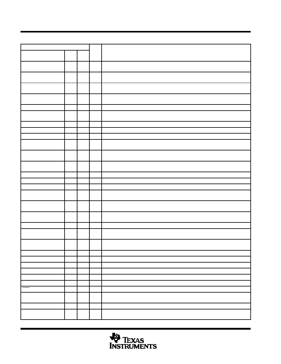
P3.4/TB3
67
E12
I/O
General-purpose digital I/O / Timer_B7 CCR3. Capture: CCI3A/CCI3B input, compare: Out3
output
P3.3/UCB0CLK
68
E11
I/O
General-purpose digital I/O / external clock input—USCI_B0/UART or SPI mode, clock
output—USCI_B0/SPI mode
P3.2/UCB0SOMI/
UCB0SCL
69
F9
I/O
General-purpose digital I/O / slave out/master in of USCI_B0/SPI mode /I2C
clock—USCI_B0/I2C mode
P3.1/UCB0SIMO/
UCB0SDA
70
D12
I/O
General-purpose digital I/O / slave in/master out of USCI_B0/SPI mode, I2C
data—USCI_B0/I2C mode
P3.0/UCB0STE
71
D11
I/O
General-purpose digital I/O / slave transmit enable—USCI_B0/SPI mode
P2.7/ADC12CLK/
DMAE0
72
E9
I/O
General-purpose digital I/O / conversion clock—12-bit ADC / DMA Channel 0 external trigger
P2.6/CAOUT
73
C12
I/O
General-purpose digital I/O / Comparator_A output
P2.5/UCA0RXD
74
C11
I/O
General-purpose digital I/O / receive data in—USCI_A0/UART or IrDA mode
P2.4/UCA0TXD
75
B12
I/O
General-purpose digital I/O / transmit data out—USCI_A0/UART or IrDA mode
P2.3/TB2
76
A11
I/O
General-purpose digital I/O / Timer_B7 CCR2. Capture: CCI2A/CCI2B input, compare: Out2
output
P2.2/TB1
77
E8
I/O
General-purpose digital I/O / Timer_B7 CCR1. Capture: CCI1A/CCI1B input, compare: Out1
output
P2.1/TB0
78
D8
I/O
General-purpose digital I/O / Timer_B7 CCR0. Capture: CCI0A/CCI0B input, compare: Out0
output
P2.0/TA2
79
A10
I/O
General-purpose digital I/O / Timer_A Capture: CCI2A input, compare: Out2 output
P1.7/CA1
80
B10
I/O
General-purpose digital I/O / Comparator_A input
P1.6/CA0
81
A9
I/O
General-purpose digital I/O / Comparator_A input
P1.5/TACLK/ACLK
82
B9
I/O
General-purpose digital I/O / Timer_A, clock signal TACLK input / ACLK output (divided by
1, 2, 4, or 8)
P1.4/TBCLK/SMCLK
83
B8
I/O
General-purpose digital I/O / input clock TBCLK—Timer_B7 / submain system clock SMCLK
output
P1.3/TBOUTH/SVSOUT
84
A8
I/O
General-purpose
digital
I/O
/
switch
all
PWM
digital
output
ports
to
high
impedance—Timer_B7 TB0 to TB6 / SVS: output of SVS comparator
P1.2/TA1
85
D7
I/O
General-purpose digital I/O / Timer_A, Capture: CCI1A input, compare: Out1 output
P1.1/TA0/MCLK
86
E7
I/O
General-purpose digital I/O / Timer_A. Capture: CCI0B input / MCLK output.
Note: TA0 is only an input on this pin / BSL receive
P1.0/TA0
87
A7
I/O
General-purpose digital I/O / Timer_A. Capture: CCI0A input, compare: Out0 output / BSL
transmit
XT2OUT
88
B7
O
Output terminal of crystal oscillator XT2
XT2IN
89
B6
I
Input port for crystal oscillator XT2. Only standard crystals can be connected.
TDO/TDI
90
A6
I/O
Test data output port. TDO/TDI data output or programming data input terminal
TDI/TCLK
91
D6
I
Test data input or test clock input. The device protection fuse is connected to TDI/TCLK.
TMS
92
E6
I
Test mode select. TMS is used as an input port for device programming and test.
TCK
93
A5
I
Test clock. TCK is the clock input port for device programming and test.
RST/NMI
94
B5
I
Reset input or nonmaskable interrupt input port
P6.0/A0/OA0I0
95
A4
I/O
General-purpose digital I/O / analog input a0—12-bit ADC / OA0 input multiplexer on
+ terminal and terminal
P6.1/A1/OA0O
96
D5
I/O
General-purpose digital I/O / analog input a1—12-bit ADC / OA0 output
P6.2/A2/OA0I1
97
B4
I/O
General-purpose digital I/O / analog input a2—12-bit ADC / OA0 input multiplexer on
+ terminal and terminal
相關(guān)PDF資料 |
PDF描述 |
|---|---|
| MSP430FG4616IZQWR | 16-BIT, FLASH, 8 MHz, RISC MICROCONTROLLER, PBGA113 |
| MSP430CG4618IZQW | 16-BIT, FLASH, 8 MHz, RISC MICROCONTROLLER, PBGA113 |
| MSP430FG478IPNR | 16-BIT, FLASH, 8 MHz, RISC MICROCONTROLLER, PQFP80 |
| MSP430FG479IPNR | 16-BIT, FLASH, 8 MHz, RISC MICROCONTROLLER, PQFP80 |
| MSP430FR5737IDA | 16-BIT, 24 MHz, RISC MICROCONTROLLER, PDSO38 |
相關(guān)代理商/技術(shù)參數(shù) |
參數(shù)描述 |
|---|---|
| MSP430CG4619IZQW | 制造商:TI 制造商全稱:Texas Instruments 功能描述:MIXED SIGNAL MICROCONTROLLER |
| MSP430E325AFZ | 制造商:Rochester Electronics LLC 功能描述: 制造商:Texas Instruments 功能描述: |
| MSP430-EASYWEB-2 | 功能描述:開發(fā)板和工具包 - MSP430 TCP/IP BRD W/ MSP430F149 10A/240V RoHS:否 制造商:Olimex Ltd. 產(chǎn)品:Development Boards 工具用于評估:MSP430F5510 核心:MSP430 接口類型:JTAG, USB 工作電源電壓:5 V |
| MSP430-EASYWEB-3 | 功能描述:開發(fā)板和工具包 - MSP430 TCP/IP BRD W/ MSP430F149 LOW PWR RoHS:否 制造商:Olimex Ltd. 產(chǎn)品:Development Boards 工具用于評估:MSP430F5510 核心:MSP430 接口類型:JTAG, USB 工作電源電壓:5 V |
| MSP430F110 | 制造商:TI 制造商全稱:Texas Instruments 功能描述:MIXED SIGNAL MICROCONTROLLER |
發(fā)布緊急采購,3分鐘左右您將得到回復(fù)。