- 您現(xiàn)在的位置:買賣IC網(wǎng) > PDF目錄224505 > MSP58C20 (Texas Instruments, Inc.) Audio-Band Converter PDF資料下載
參數(shù)資料
| 型號: | MSP58C20 |
| 廠商: | Texas Instruments, Inc. |
| 英文描述: | Audio-Band Converter |
| 中文描述: | 語音頻帶轉(zhuǎn)換器 |
| 文件頁數(shù): | 16/17頁 |
| 文件大小: | 298K |
| 代理商: | MSP58C20 |
MSP58C20
AUDIO-BAND CONVERTER
SPSS015B – DECEMBER 1993 – REVISED JULY 1996
8
POST OFFICE BOX 655303
DALLAS, TEXAS 75265
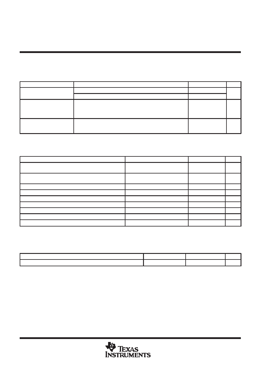
electrical characteristics over recommended ranges of supply voltage and operating free-air
temperature, ADCLK input frequency = 1.024 MHz, PWDA = L and PWAD = L (power-up mode)
(unless otherwise noted) (continued)
DAC receive characteristics (continued)
PARAMETER
TEST CONDITIONS
MIN
TYP
MAX
UNIT
Ilk
Leakage current
AOP
–10
10
A
Ilkg
Leakage current
AOM
–10
10
A
Output impedance,
differential, between
AOP and AOM
(see Note 4)
30
k
Transmit-to-receive
crosstalk
Transmit input = one frequency in 0.3-kHz to 3.4-kHz band at – 3 dBrl,
Receive channel idle,
Crosstalk measured at receive analog output
–70
dB
NOTE 4. This parameter is characterized but not tested.
timing requirements over recommended ranges of supply voltage and operating free-air
temperature
PARAMETER
TEST CONDITIONS
MIN
TYP
MAX
UNIT
tsu1
Transmit setup time at power up
(PWAD transition from H to L)
ADCLK input frequency = 1.024 MHz,
See Note 11
20
s
tsu2
Receive setup time at power up
(PWDA transition from H to L)
ADCLK input frequency = 1.024 MHz,
See Note 12
20
s
tsu3 Receive setup time, DIGS or DIGL setup before ADCLK↑
See Figure 4
50
ns
th
Receive hold time, DIGS or DIGL hold after ADCLK
↑
See Figure 4
50
ns
tc
Cycle time, ADCLK
1
s
tw1
Pulse duration, ADCLK high
470
ns
tw2
Pulse duration, ADCLK low
470
ns
tf
Fall time, ADCLK
20
ns
tr
Rise time, ADCLK
20
ns
NOTES: 11. After the setup time, the transmit channel displays normal operating characteristics.
12. After the setup time, the receive channel displays normal operating characteristics.
switching characteristic over recommended ranges of supply voltage and operating free-air
temperature
PARAMETER
TEST CONDITION
MIN
TYP
MAX
UNIT
ta
Transmit access time, ADOUT after ADCLK
↑ (see Note 4)
See Figure 3
100
ns
NOTE 4. This parameter is characterized but not tested.
相關(guān)PDF資料 |
PDF描述 |
|---|---|
| MSS2P2-E3/89A | 2 A, 20 V, SILICON, RECTIFIER DIODE |
| MSS2P3-G3/89A | 2 A, 30 V, SILICON, RECTIFIER DIODE |
| MSS2P2-G3/89A | 2 A, 20 V, SILICON, RECTIFIER DIODE |
| MSU2031L16 | low working voltage 16 MHz ROM less MCU |
| MSU2032L16 | low working voltage 16 MHz ROM less MCU |
相關(guān)代理商/技術(shù)參數(shù) |
參數(shù)描述 |
|---|---|
| MSP58C20DW | 制造商:Texas Instruments 功能描述: |
| MSP58C20DWR | 制造商:TI 制造商全稱:Texas Instruments 功能描述:AUDIO-BAND CONVERTER |
| MSP58C20S1DW | 制造商:TI 制造商全稱:Texas Instruments 功能描述:AUDIO-BAND CONVERTER |
| MSP58C20S2DW | 制造商:TI 制造商全稱:Texas Instruments 功能描述:AUDIO-BAND CONVERTER |
| MSP58P80PJM | 制造商:Rochester Electronics LLC 功能描述:- Bulk |
發(fā)布緊急采購,3分鐘左右您將得到回復(fù)。