- 您現(xiàn)在的位置:買賣IC網 > PDF目錄383642 > MT8930CP (Mitel Networks Corporation) CMOS ST-BUS⑩ FAMILY Subscriber Network Interface Circuit PDF資料下載
參數資料
| 型號: | MT8930CP |
| 廠商: | Mitel Networks Corporation |
| 英文描述: | CMOS ST-BUS⑩ FAMILY Subscriber Network Interface Circuit |
| 中文描述: | 意法半導體的CMOS總線⑩家庭用戶網絡接口電路 |
| 文件頁數: | 11/42頁 |
| 文件大?。?/td> | 323K |
| 代理商: | MT8930CP |
第1頁第2頁第3頁第4頁第5頁第6頁第7頁第8頁第9頁第10頁當前第11頁第12頁第13頁第14頁第15頁第16頁第17頁第18頁第19頁第20頁第21頁第22頁第23頁第24頁第25頁第26頁第27頁第28頁第29頁第30頁第31頁第32頁第33頁第34頁第35頁第36頁第37頁第38頁第39頁第40頁第41頁第42頁
MT8930C
9-43
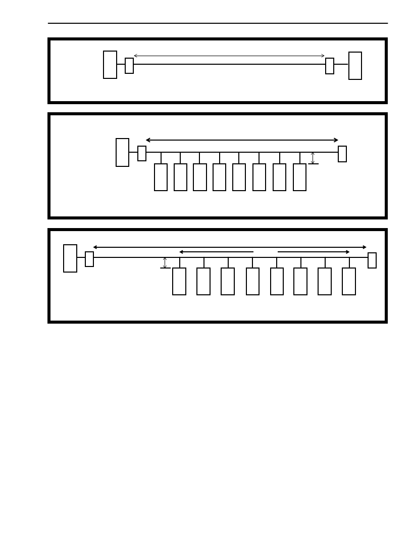
Figure 8 - Point-to-Point Configuration
Fiure 9 - Short Passive Bus Configuration, up to 8 TEs can be supported
Figure 10 - Extended Passive Bus Configuration, up to 8 TEs can be supported
NT
TE
T
R
T
R
0 - 1 Km
NT is operating in adaptive timing
TR is the line termination resistor = 100
NT
TE
T
R
T
R
TE
TE
TE
TE
TE
TE
TE
100 m for 75
impedance cable and 200 m for 150
impedance cable
100 - 200 m
NT is operating in fixed timing
TR is the line termination resistor = 100
0 - 10 m
NT is operating in adaptive timing
TR is the line termination resistor = 100
TE
TE
TE
TE
TE
TE
TE
0 - 10 m
0-500 m
0-50 m
NT
T
R
T
R
TE
TEs . All NT devices connected into the star will
receive the information transmitted by all TEs on all
branches of the star, exactly as if they were on the
same physical S-Bus. All NTs in the star
configuration must be operating in fixed timing mode.
Refer to the description of the star configuration in
the ST-BUS section.
The SNIC has one last mode of operation called the
NT slave mode. This has the effect of operating the
SNIC in network termination mode (CK/NT pin = 1)
but having the frame structure and registers
description defined by the TE mode. This can be
used where multiple subscriber loops must carry a
fixed phase relation between each line. A typical
situation is when the system is trying to synchronize
two nodes of a synchronous network. This allows
multiple TEs to share a common ST-BUS timebase.
The synchronization of the loops is established by
using the clock signals produced by a local TE as an
input timing source to the NT slave.
Adaptive Timing Operation
On power-up or after a reset, the SNIC in NT mode is
set to operate in fixed timing. To switch to adaptive
timing, the user should:
1) set the DR bit to 1
2) set the Timing bit to 1 in the C-channel
Control Register
3) wait for 100 ms period
4) proceed in using the AR and DR bits as
desired
Switching from adaptive timing mode is completed
by resetting the Timing bit.
相關PDF資料 |
PDF描述 |
|---|---|
| MT8931C | Subscriber Network Interface Circuit(用戶網絡接口電路(提供點到點或點到多點數字傳送)) |
| MT8940 | T1/CEPT Digital Trunk PLL(T1/CEPT數字中繼鎖相環(huán)) |
| MT8940 | ISO-CMOS ST-BUS⑩ FAMILY T1/CEPT Digital Trunk PLL |
| MT8940-1 | ISO-CMOS ST-BUS⑩ FAMILY T1/CEPT Digital Trunk PLL |
| MT8940AC | T1/CEPT Digital Trunk PLL |
相關代理商/技術參數 |
參數描述 |
|---|---|
| MT8930CPR | 制造商:Microsemi Corporation 功能描述: |
| MT8931B | 制造商:MITEL 制造商全稱:Mitel Networks Corporation 功能描述:Subscriber Network Interface Circuit |
| MT8931BC | 制造商:MITEL 制造商全稱:Mitel Networks Corporation 功能描述:Subscriber Network Interface Circuit |
| MT8931BE | 制造商:MITEL 制造商全稱:Mitel Networks Corporation 功能描述:Subscriber Network Interface Circuit |
| MT8931BP | 制造商:MITEL 制造商全稱:Mitel Networks Corporation 功能描述:Subscriber Network Interface Circuit |
發(fā)布緊急采購,3分鐘左右您將得到回復。