- 您現(xiàn)在的位置:買賣IC網(wǎng) > PDF目錄383644 > MT90401 (Mitel Networks Corporation) SONET/SDH System Synchronizer(SONET/SDH 系統(tǒng)同步裝置(由一個(gè)數(shù)字鎖相環(huán)組成)) PDF資料下載
參數(shù)資料
| 型號: | MT90401 |
| 廠商: | Mitel Networks Corporation |
| 英文描述: | SONET/SDH System Synchronizer(SONET/SDH 系統(tǒng)同步裝置(由一個(gè)數(shù)字鎖相環(huán)組成)) |
| 中文描述: | 的SONET / SDH系統(tǒng)的同步器(SONET / SDH的系統(tǒng)同步裝置(由一個(gè)數(shù)字鎖相環(huán)組成)) |
| 文件頁數(shù): | 3/9頁 |
| 文件大小: | 110K |
| 代理商: | MT90401 |
MT90401
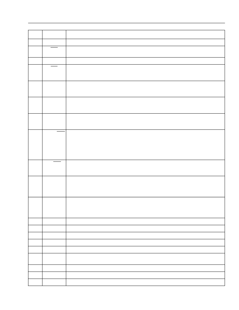
Pin Description (continued)
Product Brief
3
14
C8o
Clock 8.192MHz (CMOS Output).
This output is used for ST-BUS operation at 8.192Mb/s.
15
C4o
Clock 4.096MHz (CMOS Output).
This output is used for ST-BUS operation at 2.048Mb/s
and 4.096Mb/s.
16
C2o
Clock 2.048MHz (CMOS Output).
This output is used for ST-BUS operation at 2.048Mb/s.
17
F0o
Frame Pulse ST-BUS 2.048Mb/s (CMOS Output).
This is an 8kHz 244ns active low
framing pulse, which marks the beginning of an ST-BUS frame. This is typically used for ST-
BUS operation at 2.048Mb/s and 4.096Mb/s.
18
MS1
Mode/Control Select 1 (Input).
of F8o. See pin description for MS2. This pin performs no function if the device is not in
hardware mode.
The logic level at this input is gated in by the rising edge
19
MS2
Mode/Control Select 2 (Input).
This input determines the state (Normal, Holdover or
Freerun) of operation. The logic level at this input is gated in by the rising edge of F8o. This
pin performs no function if the device is not in hardware mode.
20
F8o
Frame Pulse Generic (CMOS Output).
This is an 8kHz 122ns active high framing pulse,
which marks the beginning of a TDM frame. This is typically used for TDM streams
operating at 8.192 Mb/s.
21
E3DS3/OC3
E3DS3 or OC-3 Selection (Input).
In Hardware Mode a low on this pin enables the
differential 155.52MHz output clock on the C155N/C155P pins; this will also cause the C34/
C44 pin to output its nominal clock frequency divided by 4. In Hardware Mode, a high on this
pin disables the differential 155.52MHz output clock on the C155N/C155P pins; this will also
cause the C34/C44 pin to output its nominal clock frequency. This pin performs no function
if the device is not in Hardware Mode.
22
E3/DS3
E3 or DS3 Selection (Input).
In Hardware Mode a low on this pin selects a clock rate of
44.736MHz for the C34/C44 pin, while a high selects a clock rate of 34.368MHz. This pin
performs no function if the device is not in hardware mode.
23
SEC
Secondary Reference (Input).
(falling edge) used for synchronization. One of four possible frequencies (8kHz, 1.544MHz,
2.048MHz or 19.44MHz) may be used. In hardware mode the selection of the input
reference is based upon the MS1, MS2 and RSEL control inputs.
This is one of two (PRI & SEC) input reference sources
24
PRI
Primary Reference (Input).
(falling edge) used for synchronization. One of four possible frequencies (8kHz, 1.544MHz,
2.048MHz or 19.44MHz) may be used. In hardware mode the selection of the input
reference is based upon the MS1, MS2 and RSEL control inputs.
This is one of two (PRI & SEC) input reference sources
25
V
SS2
IC
Digital ground.
0 Volts
26
Internal Connection.
Leave unconnected
27
V
SS3
PLL
V
DD2
PLL
VDD
3
C155N,
C155P
Analog ground.
0 Volts
Positive Analog Power Supply.
Analog supply (+3.3V
±
5%).
Positive Power Supply.
Digital supply (+3.3V
±
5%).
LVDS 155.52 MHz (Output)).
Differential outputs generating a 155.52MHz clock
28
29
30
31
32
VSS
4
IC
Digital ground.
0 Volts
33
Internal Connection.
Leave unconnected
34
Tdo
IEEE 1149.1a Test Data Output (Output).
If not used, this pin should be left unconnected.
Pin #
Name
Description
相關(guān)PDF資料 |
PDF描述 |
|---|---|
| MT9040 | T1/E1 Synchronizer(T1/E1 系統(tǒng)同步裝置(由一個(gè)數(shù)字鎖相環(huán)組成)) |
| MT9041A | () |
| MT9041B | T1/E1 System Synchronizer(T1/E1系統(tǒng)同步裝置(由一個(gè)數(shù)字鎖相環(huán)組成)) |
| MT9042B | () |
| MT9042C | Multitrunk System Synchronizer(多中繼系統(tǒng)同步裝置) |
相關(guān)代理商/技術(shù)參數(shù) |
參數(shù)描述 |
|---|---|
| MT90401AB | 制造商:ZARLINK 制造商全稱:Zarlink Semiconductor Inc 功能描述:SONET/SDH System Synchronizer |
| MT90401AB1 | 制造商:Microsemi Corporation 功能描述:FRAMER SDH/SONET 3.3V 80LQFP EP - Trays 制造商:MICROSEMI CONSUMER MEDICAL PRODUCT GROUP 功能描述:IC SYNCHRONIZER SONET/SDH 80LQFP 制造商:Microsemi Corporation 功能描述:IC SYNCHRONIZER SONET/SDH 80LQFP |
| MT9040AN | 制造商:ZARLINK 制造商全稱:Zarlink Semiconductor Inc 功能描述:T1/E1 Synchronizer |
| MT9040AN1 | 制造商:Microsemi Corporation 功能描述:FRAMER E1 /T1 3.3V 48SSOP - Rail/Tube |
| MT9040ANR1 | 制造商:Microsemi Corporation 功能描述:FRAMER E1 /T1 3.3V 48SSOP - Tape and Reel |
發(fā)布緊急采購,3分鐘左右您將得到回復(fù)。