- 您現(xiàn)在的位置:買賣IC網(wǎng) > PDF目錄376245 > OP493 (Analog Devices, Inc.) Precision, Micropower Operational Amplifiers(精密的微功率四運放) PDF資料下載
參數(shù)資料
| 型號: | OP493 |
| 廠商: | Analog Devices, Inc. |
| 英文描述: | Precision, Micropower Operational Amplifiers(精密的微功率四運放) |
| 中文描述: | 精密,微功耗運算放大器(精密的微功率四運放) |
| 文件頁數(shù): | 6/16頁 |
| 文件大?。?/td> | 273K |
| 代理商: | OP493 |

REV. A
–6–
OP193/OP293/OP493
ABSOLUT E MAX IMUM RAT INGS
1
Supply Voltage . . . . . . . . . . . . . . . . . . . . . . . . . . . . . . . .
±
18 V
Input Voltage
2
. . . . . . . . . . . . . . . . . . . . . . . . . . . . . . . .
±
18 V
Differential Input Voltage
2
. . . . . . . . . . . . . . . . . . . . . . .
±
18 V
Output Short-Circuit Duration to Gnd . . . . . . . . . . Indefinite
Storage T emperature Range
P, S Package . . . . . . . . . . . . . . . . . . . . . . . –65
°
C to +150
°
C
Operating T emperature Range
OP193/OP293/OP493E, F . . . . . . . . . . . . –40
°
C to +125
°
C
Junction T emperature Range
P, S Package . . . . . . . . . . . . . . . . . . . . . . . –65
°
C to +150
°
C
Lead T emperature Range (Soldering, 60 sec) . . . . . . . +300
°
C
Package T ype
θ
JA3
θ
JC
Units
8-Pin Plastic DIP (P)
8-Pin SOIC (S)
14-Pin Plastic DIP (P)
16-Pin SOL (S)
103
158
83
92
43
43
39
27
°
C/W
°
C/W
°
C/W
°
C/W
NOT ES
1
Absolute maximum ratings apply to both DICE and packaged parts, unless
otherwise noted.
2
For supply voltages less than
±
18 V, the input voltage is limited to the supply
voltage.
3
θ
is specified for the worst case conditions, i.e.,
θ
is specified for device in socket
for P-DIP, and
θ
JA
is specified for device soldered in circuit board for SOIC
package.
WARNING!
ESD SENSITIVE DEVICE
C AUT ION
ESD (electrostatic discharge) sensitive device. Electrostatic charges as high as 4000 V readily
accumulate on the human body and test equipment and can discharge without detection.
Although the OP193/OP293/OP493 feature proprietary ESD protection circuitry, permanent
damage may occur on devices subjected to high energy electrostatic discharges. T herefore,
proper ESD precautions are recommended to avoid performance degradation or loss of
functionality.
ORDE RING GUIDE
T emperature
Range
Package
Description
Package
Option
Model
OP193EP
OP193ES
OP193ES-REEL
OP193ES-REEL7
OP193FP
OP193FS
OP193FS-REEL
OP193FS-REEL7
OP193GBC
OP293EP
OP293ES
OP293ES-REEL
OP293ES-REEL7
OP293FP
OP293FS
OP293FS-REEL
OP293FS-REEL7
OP293GBC
OP493EP
OP493ES
OP493ES-REEL
OP493FP
OP493FS
OP493FS-REEL
OP493GBC
–40
°
C to +125
°
C
–40
°
C to +125
°
C
–40
°
C to +125
°
C
–40
°
C to +125
°
C
–40
°
C to +125
°
C
–40
°
C to +125
°
C
–40
°
C to +125
°
C
–40
°
C to +125
°
C
+25
°
C
–40
°
C to +125
°
C
–40
°
C to +125
°
C
–40
°
C to +125
°
C
–40
°
C to +125
°
C
–40
°
C to +125
°
C
–40
°
C to +125
°
C
–40
°
C to +125
°
C
–40
°
C to +125
°
C
+25
°
C
–40
°
C to +125
°
C
–40
°
C to +125
°
C
–40
°
C to +125
°
C
–40
°
C to +125
°
C
–40
°
C to +125
°
C
–40
°
C to +125
°
C
+25
°
C
8-Pin Plastic DIP
8-Pin SOIC
8-Pin SOIC
8-Pin SOIC
8-Pin Plastic DIP
8-Pin SOIC
8-Pin SOIC
8-Pin SOIC
DICE
8-Pin Plastic DIP
8-Pin SOIC
8-Pin SOIC
8-Pin SOIC
8-Pin Plastic DIP
8-Pin SOIC
8-Pin SOIC
8-Pin SOIC
DICE
14-Pin Plastic DIP
16-Pin SOL
16-Pin SOL
14-Pin Plastic DIP
16-Pin SOL
16-Pin SOL
DICE
N-8
SO-8
SO-8
SO-8
N-8
SO-8
SO-8
SO-8
N-8
SO-8
SO-8
SO-8
N-8
SO-8
SO-8
SO-8
N-14
SOL-16
SOL-16
N-14
SOL-16
SOL-16
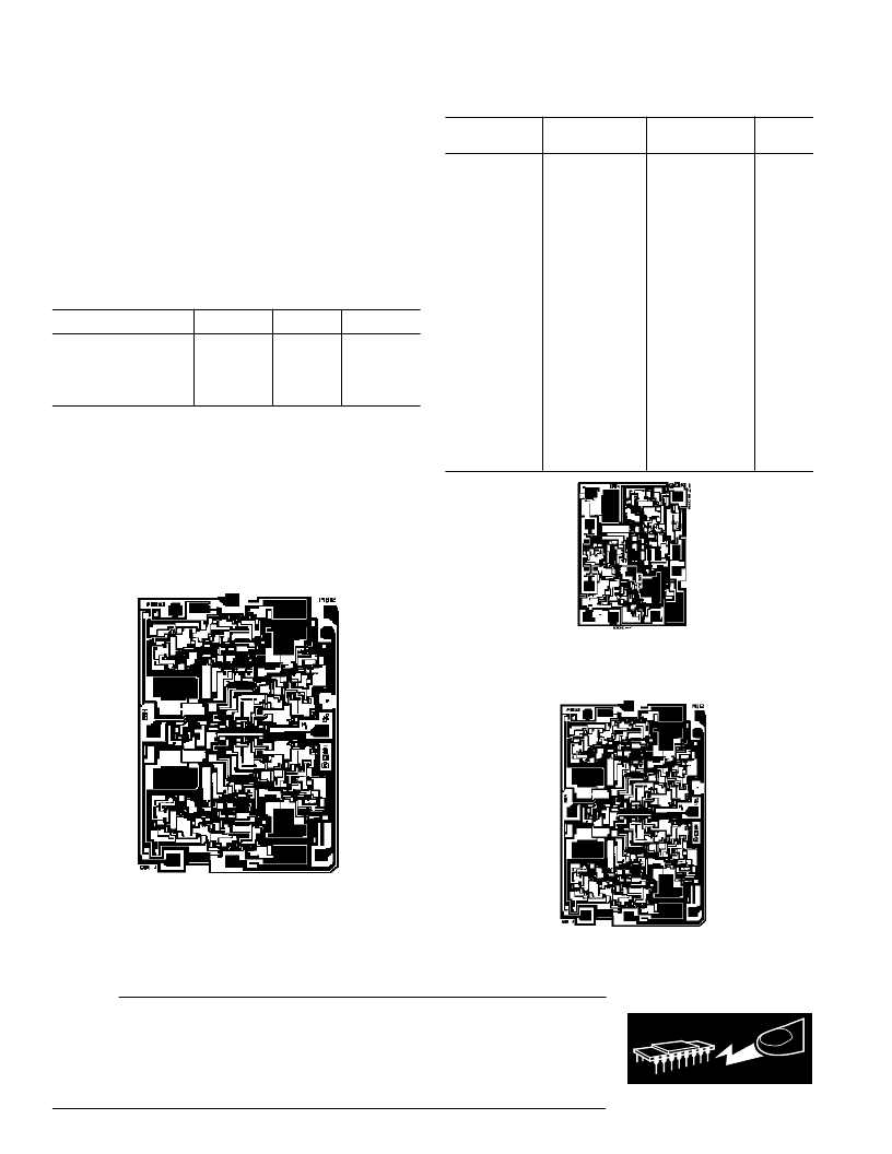
DICE CHARACT E RIST ICS
2
1
3
4
6
5
8
7
OP493 Die Size 0.106
×
0.143 Inch, 15,158 Sq. Mils Substrate
(Die Backside) Is Connected to V– Transistor Count, 215
2
1
3
4
6
5
7
OP193 Die Size 0.070
×
0.055 Inch, 3,850 Sq. Mils Substrate
(Die Backside) Is Connected to V– Transistor Count, 55
2
1
3
4
6
5
8
7
OP293 Die Size 0.072
×
0.110 Inch, 7,920 Sq. Mils Substrate
(Die Backside) Is Connected to V– Transistor Count, 105
相關(guān)PDF資料 |
PDF描述 |
|---|---|
| OP497GS | Precision Picoampere Input Current Quad Operational Amplifier |
| OP497 | Precision Picoampere Input Current Quad Operational Amplifier |
| OP497AY | Precision Picoampere Input Current Quad Operational Amplifier |
| OP497CY | Precision Picoampere Input Current Quad Operational Amplifier |
| OP497FP | Precision Picoampere Input Current Quad Operational Amplifier |
相關(guān)代理商/技術(shù)參數(shù) |
參數(shù)描述 |
|---|---|
| OP4930003SR | 制造商:Analog Devices 功能描述: |
| OP493EP | 制造商:Rochester Electronics LLC 功能描述:MICROPOWER RAIL/RAIL - Bulk |
| OP493ES | 制造商:AD 制造商全稱:Analog Devices 功能描述:Precision, Micropower Operational Amplifiers |
| OP493ES-REEL | 制造商:AD 制造商全稱:Analog Devices 功能描述:Precision, Micropower Operational Amplifiers |
| OP493FP | 制造商:Rochester Electronics LLC 功能描述:MICROPOWER RAIL/RAIL - Bulk 制造商:Analog Devices 功能描述: |
發(fā)布緊急采購,3分鐘左右您將得到回復(fù)。