- 您現(xiàn)在的位置:買賣IC網(wǎng) > PDF目錄367644 > P172ABCJ PV 16C 16#16 SKT RECP PDF資料下載
參數(shù)資料
| 型號: | P172ABCJ |
| 英文描述: | PV 16C 16#16 SKT RECP |
| 中文描述: | P172型接收機 |
| 文件頁數(shù): | 3/8頁 |
| 文件大小: | 89K |
| 代理商: | P172ABCJ |

3
Agere Systems Inc.
Advance Data Sheet
August 2001
P172-Type Receiver
Electrical Characteristics
Minimum and maximum values specified over operating case temperature range and end of life (EOL), and typical
values are for 25
°
C and beginning of life (BOL), unless otherwise specified
* The resistance of the thermistor is inversely proportional to the temperature. The temperature can be calculated from the resistance value
using the Steinhart-Hart equation: 1/T = A + B ln(R) + C ln(R)
3
;
where A, B, and C are constants: A = 1.0267 x 10
–3
,
B = 2.565 x 10
–4
,
C = 4.5421 x 10
–8
.
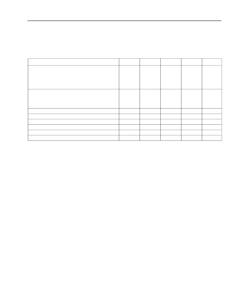
Table 2. Electrical Characteristic
Parameter
Symbol
Min
Typ
Max
Unit
dc Power Supply Voltages:
Positive Supply
APD Operating Bias Voltage
APD Operating Voltage Temperature Coefficient
PIN Operating Bias Voltage
dc Power Supply Currents:
Positive Supply
APD Bias Supply at V
OP
PIN Bias Supply at V
OP
dc Power Dissipation
Small Signal (<10
μ
A) Transimpedance
Input Noise Current (100 kHz—2 GHz)
Output Return Loss (130 MHz—5 GHz)
3 dB Bandwidth
Thermistor resistance at 25
°
C*
V
CC
V
OP
—
V
OP
3.15
45
0.07
3.0
3.3
—
—
5.0
3.45
70
0.14
15
V
V
V/
°
C
V
I
CC
I
APD
I
PIN
P
DISS
T
z
N
rms
S
22
f
C
R
TH
—
—
—
—
1.7
—
—
1.7
9.5
55
—
—
200
2.5
322
–15
2.0
10
101
4
4
350
3.1
466
–9
—
10.5
mA
mA
mA
mW
k
nArms
dB
GHz
k
相關(guān)PDF資料 |
PDF描述 |
|---|---|
| P172ABCS | P172-Type Receiver |
| P172ACCA | PV SERIES |
| P172ACCF | CANMS3470W20-39SL/C |
| P172ACCJ | CANMS3470W20-41PL/C |
| P172ACCS | PV SERIES |
相關(guān)代理商/技術(shù)參數(shù) |
參數(shù)描述 |
|---|---|
| P172ABCS | 制造商:AGERE 制造商全稱:AGERE 功能描述:P172-Type Receiver |
| P172ACCA | 制造商:AGERE 制造商全稱:AGERE 功能描述:P172-Type Receiver |
| P172ACCF | 制造商:AGERE 制造商全稱:AGERE 功能描述:P172-Type Receiver |
| P172ACCJ | 制造商:AGERE 制造商全稱:AGERE 功能描述:P172-Type Receiver |
| P172ACCS | 制造商:AGERE 制造商全稱:AGERE 功能描述:P172-Type Receiver |
發(fā)布緊急采購,3分鐘左右您將得到回復。