- 您現在的位置:買賣IC網 > PDF目錄378039 > PBD35171 (ERICSSON) Stepper Motor Drive Circuit PDF資料下載
參數資料
| 型號: | PBD35171 |
| 廠商: | ERICSSON |
| 英文描述: | Stepper Motor Drive Circuit |
| 中文描述: | 步進電機驅動電路 |
| 文件頁數: | 9/10頁 |
| 文件大?。?/td> | 135K |
| 代理商: | PBD35171 |
PBD 3517/1
9
V
Z
R
R
Ext
i
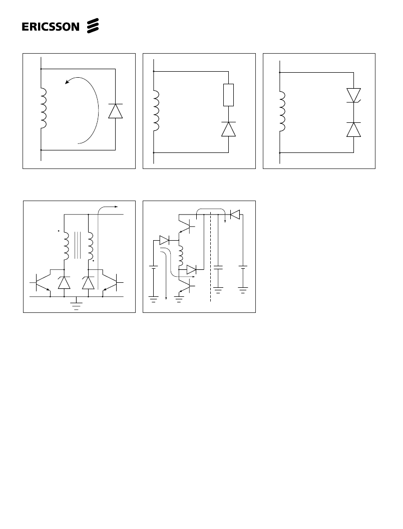
Figure 24. Power return turn-off circuit.
Figure 25. Power return turn-off circuit for
bilevel .
Figure 22. Resistance turn-off circuit.
Figure 23. Zener diode turn-off circuit.
Figure 21. Diode turn-off circuit.
7.
To change actual motor rotation
direction, exchange motor connec-
tions at P
A1
and P
A2
(or P
B1
and P
B2
).
Half-stepping.
in the half-step mode,
the power input to the motor alter-
nates between one or two phase
windings. In half-step mode, motor
resonances are reduced. In a two-
phase motor, the electrical phase
shift between the windings is 90
degrees. The torque developed is the
vector sum of the two windings
energized. Therefore, when only one
winding is energized, which is the
case in half-step mode for every
second step, the torque of the motor
is reduced by approximately 30%.
This causes a torque ripple.
8.
9.
Ramping.
Every drive system has
inertia which must be considered in
the drive scheme. The rotor and load
inertia plays a big role at higher
speeds. Unlike the DC motor, the
stepper motor is a synchronous
motor and does not change speed
due to load variations. Examination of
typical stepper motors’ torque versus
speed curves indicates a sharp
torque drop-off for the start-stop
without error curve. The reason for
this is that the torque requirements
increase by the cube of the speed
change. As it can be seen, for good
motor performance, controlled
acceleration and deceleration should
be considered.
User Hints
1.
Never disconnect ICs or PC-boards
when power is supplied.
2.
If second supply is not used, discon-
nect and leave open V
, L
, L
B
, and
RC. Preferably replace the V
supply diodes (D1, D2) with a straight
connection.
Remember that excessive voltages
might be generated by the motor,
even though clamping diodes are
used.
Choice of motor.
Choose a motor
that is rated for the current you need
to establish desired torque. A high
supply voltage will gain better
stepping performance. If the motor is
not specified for the V
voltage, a
current limiting resistor will be
3.
4.
necessary to connect in series with
center tap. This changes the L/R
time constant.
5.
Never use L
or L
for continuous
output at high currents. L
and L
on-
time can be altered by changing the
RC net. An alternative is to trigger
the mono-flip-flop by taking a STEP
and then externally pulling the RC
pin (12) low (0V) for the desired on-
time.
6.
Avoid V
and V
power supplies
with serial diodes (without filter
capacitor) and/or common ground
with V
. The common place for
ground should be as close as
possible to the IC’s ground pin (pin
3).
V
1
V
2
C
S
0V
Power supply
相關PDF資料 |
PDF描述 |
|---|---|
| PBD35171N | Stepper Motor Drive Circuit |
| PBD35171SO | Stepper Motor Drive Circuit |
| PBD3534 | DTMF Generator |
| PBL3762 | Subcriber Line Interface Circuit |
| PBL3764 | SUBSCRIBER LINE INTERFACE CIRCUIT |
相關代理商/技術參數 |
參數描述 |
|---|---|
| PBD3517-1 | 制造商:ERICSSON 制造商全稱:Ericsson 功能描述:Stepper Motor Drive Circuit |
| PBD35171N | 制造商:ERICSSON 制造商全稱:Ericsson 功能描述:Stepper Motor Drive Circuit |
| PBD35171SO | 制造商:ERICSSON 制造商全稱:Ericsson 功能描述:Stepper Motor Drive Circuit |
| PBD3517N | 制造商:未知廠家 制造商全稱:未知廠家 功能描述:Industrial Control IC |
| PBD3534 | 制造商:ERICSSON 制造商全稱:Ericsson 功能描述:DTMF Generator |
發(fā)布緊急采購,3分鐘左右您將得到回復。