- 您現(xiàn)在的位置:買賣IC網(wǎng) > PDF目錄378039 > PBL3770A (ERICSSON) High Performance Stepper Motor Drive Circuit PDF資料下載
參數(shù)資料
| 型號(hào): | PBL3770A |
| 廠商: | ERICSSON |
| 英文描述: | High Performance Stepper Motor Drive Circuit |
| 中文描述: | 高性能步進(jìn)電機(jī)驅(qū)動(dòng)電路 |
| 文件頁數(shù): | 5/8頁 |
| 文件大小: | 140K |
| 代理商: | PBL3770A |
PBL 3770A
5
Functional Description
The PBL 3770A is intended to drive a
bipolar constant current through one
winding of a 2-phase stepper motor.
Current control is achieved through
switched-mode regulation, see figure 5
and 6.
Three different current levels and zero
current can be selected by the input
logic.
The circuit contains the following
functional blocks:
Input logic
Current sense
Single-pulse generator
Output stage
Input logic
Phase input.
The phase input
determines the direction of the current in
the motor winding. High input forces the
current from terminal M
to M
and low
input from terminal M
to M
. A Schmitt
trigger provides noise immunity and a
delay circuit eliminates the risk of cross
conduction in the output stage during a
phase shift.
Half- and full-step operation is
possible.
Current level selection.
The status of I
0
and I
inputs determines the current level
in the motor winding. Three fixed current
levels can be selected according to the
table below.
Motor current
I0
L
H
L
H
I1
L
L
H
H
High level
Medium level
Low level
Zero current
The specific values of the different
current levels are determined by the
reference voltage V
together with the
value of the sensing resistor R
.
The peak motor current can be
calculated as follows:
i
m
= (V
R
0.080) / R
S
[A], at 100% level
The motor current can also be
continuously varied by modulating the
voltage reference input.
100%
60%
20%
0%
Current sensor
The current sensor contains a reference
voltage divider and three comparators
for measuring each of the selectable
current levels. The motor current is
sensed as a voltage drop across the
current sensing resistor, R
, and
compared with one of the voltage
references from the divider. When the
two voltages are equal, the compara-tor
triggers the single-pulse generator. Only
one comparator at a time is activa-ted by
the input logic.
Single-pulse generator
The pulse generator is a monostable
multivibrator triggered on the positive
edge of the comparator output. The
multivibrator output is high during the
pulse time, t
, which is determined by
the timing components R
T
and C
T
.
t
off
= 0.69 R
T
C
T
The single pulse switches off the
power feed to the motor winding,
causing the winding to decrease during
t
off
.
If a new trigger signal should occur
during t
off
, it is ignored.
Output stage
The output stage contains four
transistors and two diodes, connected in
an H-bridge. Note that the upper
recirculation diodes are connected to the
circuit externally. The two sinking
transistors are used to switch the power
supplied to the motor winding, thus
driving a constant current through the
winding. See figures 5 and 6.
Overload protection
The circuit is equipped with a thermal
shut-down function, which will limit the
junction temperature. The output current
will be reduced if the maximum permis-
sible junction temperature is exceeded.
It should be noted, however, that it is not
short circuit protected.
Operation
When a voltage V
is applied across
the motor winding, the current rise
follows the equation:
i
m
= (V
MM
/ R) (1 - e
-(R t ) / L
)
R = Winding resistance
L = Winding inductance
t
= time
(see figure 6, arrow 1)
The motor current appears across the
external sensing resistor, R
, as an
analog voltage. This voltage is fed
through a low-pass filter, R
C
, to the
voltage comparator input (pin 10). At the
moment the sensed voltage rises above
the comparator threshold voltage, the
monostable is triggered and its output
turns off the conducting sink transistor.
The polarity across the motor winding
reverses and the current is forced to
circulate through the appropriate upper
protection diode back through the source
transistor (see figure 6, arrow 2).
After the monostable has timed out,
the current has decayed and the analog
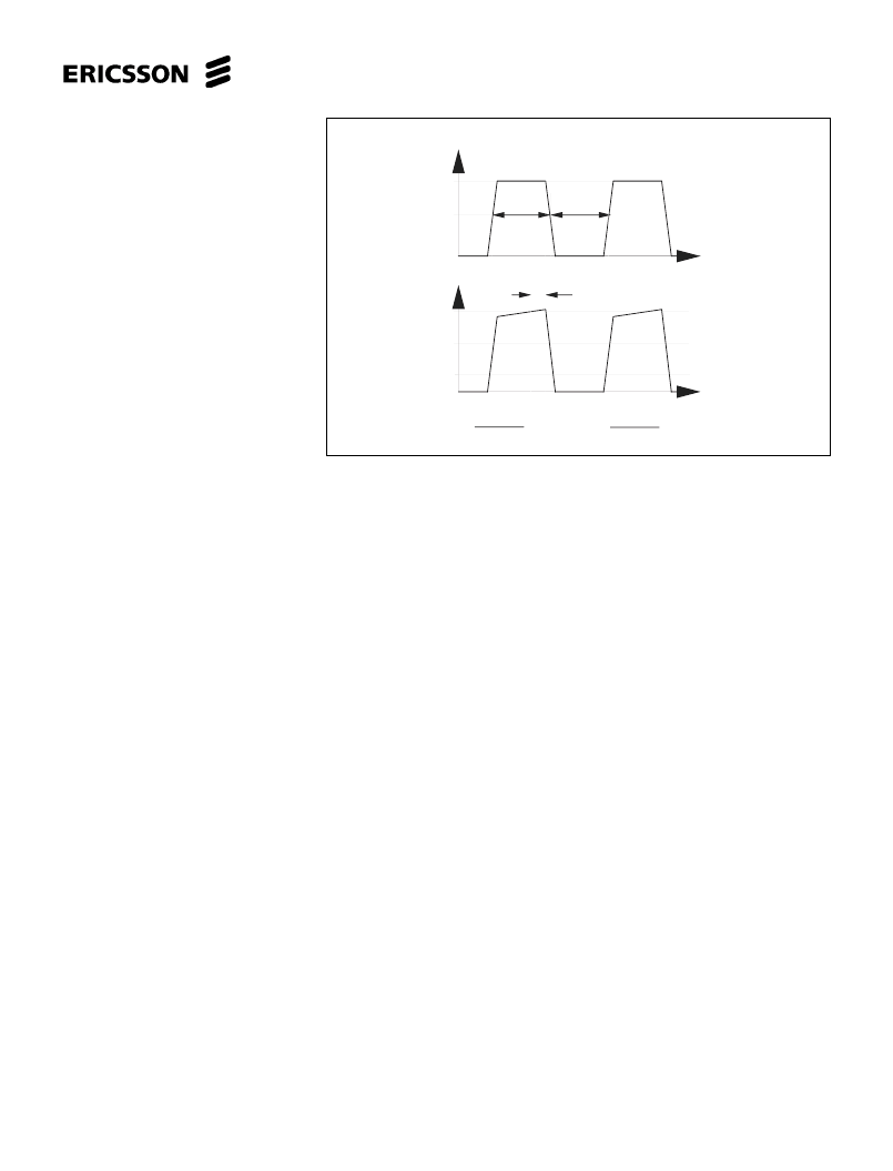
Figure 4. Definition of terms.
| V – V |
1/2
1
V
CH
t
on
t
off
f =
t
on
t
off
+
Normalized
V
E
t
d
t
t
V
CM
V
CL
D =
t
on
t
off
+
1
t
on
相關(guān)PDF資料 |
PDF描述 |
|---|---|
| PBL3770ANS | KPTC 6C 6#20 SKT PLUG |
| PBL3770ASOS | KPTC 6C 6#20 SKT PLUG |
| PBL3770ASOT | KPTC 6C 6#20 SKT PLUG |
| PBL3771QN | Box-shaped pin header, Discrete wire crimping connection, Discrete wire connectors; HRS No: 543-0071-8 00; No. of Positions: 9; Connector Type: Wire; Contact Gender: Male; Contact Spacing (mm): 2; Terminal Pitch (mm): 2; Current Rating(Amps)(Max.): 3; Operating Temperature Range (degrees C): -30 to 85; General Description: In-line plug; Crimping |
| PBL3771 | KPTC 10C 10#20 PIN PLUG |
相關(guān)代理商/技術(shù)參數(shù) |
參數(shù)描述 |
|---|---|
| PBL3770AN | 制造商:Evox Rifa / KEMET 功能描述:Motor Controller Circuit, 16 Pin, DIP |
| PBL3770ANS | 制造商:ERICSSON 制造商全稱:Ericsson 功能描述:High Performance Stepper Motor Drive Circuit |
| PBL3770AQN | 制造商:未知廠家 制造商全稱:未知廠家 功能描述:Stepper Motor Controller/Driver |
| PBL3770AQNS | 制造商:ERICSSON 制造商全稱:Ericsson 功能描述:High Performance Stepper Motor Drive Circuit |
| PBL3770AQNT | 制造商:ERICSSON 制造商全稱:Ericsson 功能描述:High Performance Stepper Motor Drive Circuit |
發(fā)布緊急采購(gòu),3分鐘左右您將得到回復(fù)。