- 您現(xiàn)在的位置:買賣IC網(wǎng) > PDF目錄378039 > PBL37711SO (ERICSSON) KPTC 3C 3#16 SKT PLUG PDF資料下載
參數(shù)資料
| 型號: | PBL37711SO |
| 廠商: | ERICSSON |
| 英文描述: | KPTC 3C 3#16 SKT PLUG |
| 中文描述: | 精密步進電機驅(qū)動器 |
| 文件頁數(shù): | 5/8頁 |
| 文件大小: | 154K |
| 代理商: | PBL37711SO |
PBL 3771/1
5
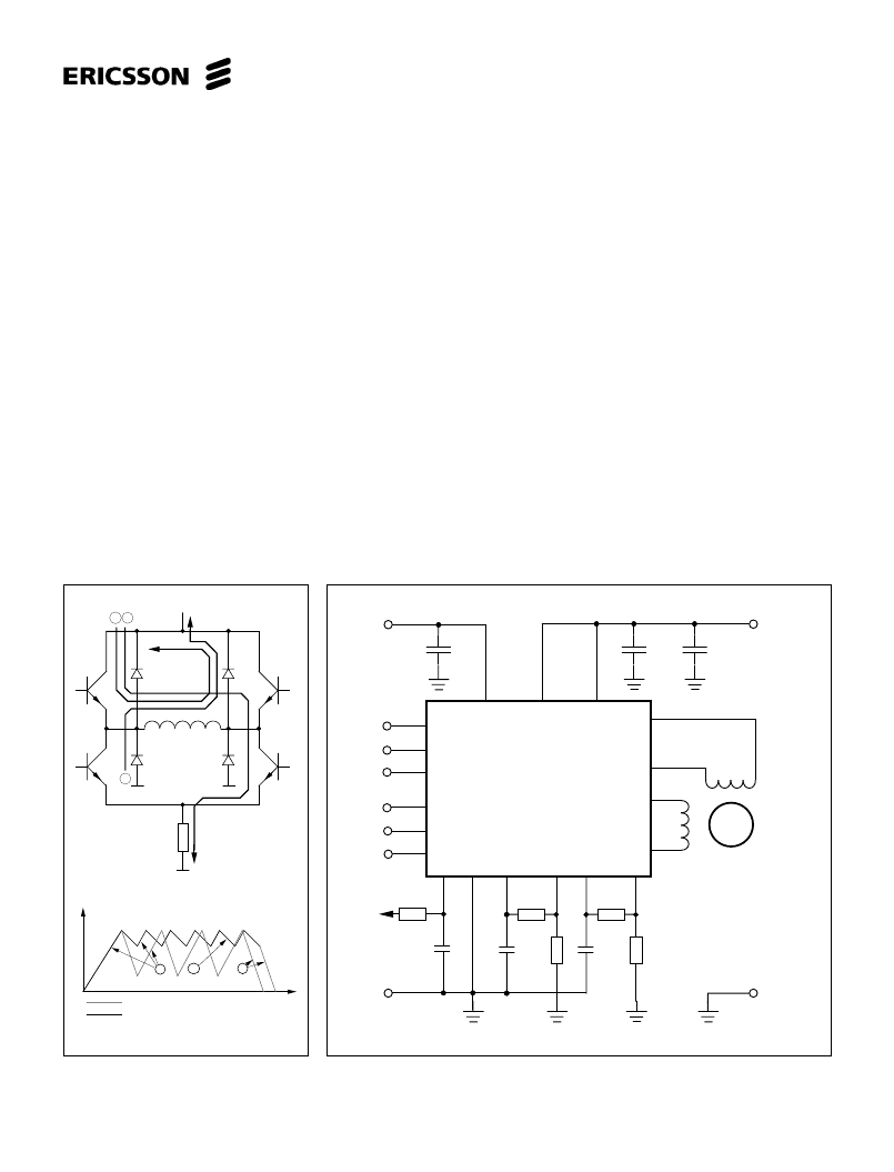
FAST Current Decay
SLOW Current Decay
Motor Current
Time
1
3
2
Figure 5. Output stage with current paths
during turn -on, turn-off and phase shift.
Figure 6. Typical stepper motor application with PBL 3771/1.
Functional Description
Each channel of the PBL 3771/1
consists of the following sections: an
H-bridge output stage, capable of driving
up to 650 mA continuous motor current
(or 500 mA, both channels driven), a
logic section that controls the output
transistors, an S-R flip-flop, and two
comparators. The oscillator is common
to both channels.
Constant current control is achieved
by switching the current to the windings.
This is done by sensing the (peak)
voltage across a current-sensing
resistor, R
, effectively connected in
series with the motor winding, and
feeding that voltage back to a
comparator. When the motor current
reaches a threshold level, determined by
the voltage at the reference input, V
,
the comparator resets the flip-flop, which
turns off the output transistors. The
current decreases until the clock
oscillator triggers the flip-flop, which
turns on the output transistors again,
and the cycle is repeated.
The current-decay rate during the
turn-off portion of the switching cycle,
can be selected fast or slow by the CD
input.
In slow current-decay mode, only one
of the lower transistors in the H-bridge
(those closest to the negative supply) is
switched on and off, while one of the
upper transistors is held constantly on.
During turn-off, the current recirculates
through the upper transistor (which one
depends on current direction) and the
corresponding free-wheeling diode
connected to V
, see figure 5.
In fast current decay mode, both the
upper and lower transistors are
switched. During the off-time, the
freewheeling current is opposed by the
supply voltage, causing a rapid dis-
charge of energy in the winding.
Fast current decay may be required in
half- and microstepping applications
when rapid changes of motor current are
necessary. Slow current decay,
however, gives less current ripple, and
should always be selected, if possible, to
mini-mize core losses and switching
noise.
Applications Information
Current control
The output current to the motor winding
is mainly determined by the voltage at
the reference input and the value of the
sensing resistor, R
.
Chopping frequency, winding
inductance, and supply voltage will affect
the current level, but to much less
extent. Fast current decay setting will
produce somewhat lower (average)
current than slow current decay. The
peak current through the sensing
resistor (and motor winding) can be
expressed as:
I
M,peak
= 0.18 (V
R
/ R
S
)
i.e., with a recommended value of 1 ohm
for the sensing resistor, R
, a 2.5 V
reference voltage will produce an output
current of approximately 450 mA. To
improve noise immunity on the V
input,
the control range may be increased to
5 volts if R
S
is correspondingly changed
to 2 ohms.
[A]
3
2 1
R
s
7
8
9
16
15
14
Phase
CD
V
Phase
CD
V
RC
12
1
1
2
2
R1
R2
E
C
E
2
C
GND
PBL
3771/1
15 kW
3 300 pF
1.0 W
1.0 W
M
M
M
M
A1
B1
A2
B2
V
CC
V
V
MM1
MM2
+5 V
4
1
19
22
11
3
20
5, 6,
17, 18
13
21
10
1
1
2
2
RS
STEPPER
MOTOR
V
Pin numbers refer
to DIL package.
GND (V
)
1 kW
1 kW
820 pF
820 pF
RS
0.1 mF
0.1 mF
+
10 mF
V (+5 V)
GND
(V )
MM
相關(guān)PDF資料 |
PDF描述 |
|---|---|
| PBL3771N | CONNECTOR GERMAN |
| PBL3771SO | KPTC 8C 8#20 SKT PLUG |
| PBL3772 | DUAL STEPPER MOTOR DRIVER |
| PBL3772N | DUAL STEPPER MOTOR DRIVER |
| PBL3772QN | DUAL STEPPER MOTOR DRIVER |
相關(guān)代理商/技術(shù)參數(shù) |
參數(shù)描述 |
|---|---|
| PBL3771N | 制造商:ERICSSON 制造商全稱:Ericsson 功能描述:Precision Stepper Motor Driver |
| PBL3771QN | 制造商:ERICSSON 制造商全稱:Ericsson 功能描述:Precision Stepper Motor Driver |
| PBL3771SO | 制造商:ERICSSON 制造商全稱:Ericsson 功能描述:Precision Stepper Motor Driver |
| PBL3772 | 制造商:ERC 功能描述:3772 ERICSON S4F2A NOT DIP |
| PBL3772N | 制造商:ERICSSON 制造商全稱:Ericsson 功能描述:DUAL STEPPER MOTOR DRIVER |
發(fā)布緊急采購,3分鐘左右您將得到回復(fù)。