- 您現(xiàn)在的位置:買賣IC網(wǎng) > PDF目錄369957 > PD64012 (Electronic Theatre Controls, Inc.) 12-channel PoE Manager PDF資料下載
參數(shù)資料
| 型號: | PD64012 |
| 廠商: | Electronic Theatre Controls, Inc. |
| 英文描述: | 12-channel PoE Manager |
| 中文描述: | 12通道供電管理 |
| 文件頁數(shù): | 7/16頁 |
| 文件大小: | 496K |
| 代理商: | PD64012 |

PD64012
12-CHANNEL PoE MANAGER
PIN
51.
AGND
52.
PORT_SENSE5
53.
V
PORT_NEG4
54.
PORT_SENSE4
55.
V
PORT_NEG3
56.
PORT_SENSE3
57.
PORT_SENSE2
58.
V
PORT_NEG2
59.
PORT_SENSE1
60.
V
PORT_NEG1
61.
PORT_SENSE0
62.
SENSE_NEG
63.
V
PORT_NEG0
64.
Reserved
PIN NAME
PIN TYPE
Supply
Analog I/O
Analog I/O
Analog I/O
Analog I/O
Analog I/O
Analog I/O
Analog I/O
Analog I/O
Analog I/O
Analog I/O
Analog I/O
Analog I/O
TBD
PIN DESCRIPTION
Analog ground
Channel current monitoring
Port 4 negative voltage feeding
Channel current monitoring
Port 3 negative voltage feeding
Channel current monitoring
Channel current monitoring
Port 2 negative voltage feeding
Channel current monitoring
Port 1 negative voltage feeding
Channel current monitoring
Port sense reference
Port 0 negative voltage feeding
Not connected
Functional Description
________
Operational Modes
The PD64012 supports two main modes of operation,
based on two different architectures, as described
hereafter. The two modes are: Enhanced mode and
Automatic mode.
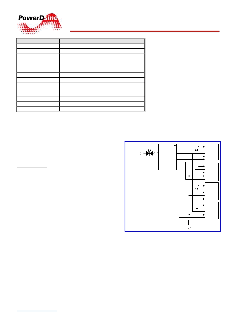
Enhanced mode – in this mode of operation, the
PD64012s communicate with the PD63000 PoE
MCU (dedicated MCU for Power over Ethernet
tasks), through a Serial Parallel Interface (SPI) bus.
In this mode, all PD64012s are directly connected to
the PD63000 through the SPI, in slave mode. The
MCU is used for additional Power over Ethernet
features, such as:
Legacy PDs detection (including Cisco discovery)
Enhanced power management algorithms
LED indicators support
Port matrix control
Communication protocol translator.
The switch host CPU communicates with the
PD63000, via an isolated I
2
C or UART bus, as shown
in Figure 3.
www.powerdsine.com
06-0003-058 (Rev. 2.8) / 5 August 2004
PD64012
#00
PD64012
#01
PD64012
#10
PD64012
#11
MISO
SCK
MOSI
I/O Opto
Host
CPU
CS0_N
CS1_N
CS0_N
CS1_N
CS0_N
CS1_N
CS0_N
CS1_N
CS3
CS2
CS1
CS0
I
2
C or UART
SPI Bus
PD63000
PoE MCU
Pull-down
resistor
Figure 3: Enhanced Mode
PowerDsine 2003
Information in this document subject
to change without prior notice.
7
相關PDF資料 |
PDF描述 |
|---|---|
| PD65-25MC | Analog IC |
| PD65-10HC | Analog IC |
| PD65-10LC | Analog IC |
| PD65-10MC | Analog IC |
| PD65-12HC | Analog IC |
相關代理商/技術參數(shù) |
參數(shù)描述 |
|---|---|
| PD64012G | 制造商:Microsemi Corporation 功能描述:POE PSE MANAGER - Bulk |
| PD64012GH | 制造商:Microsemi Corporation 功能描述:POE PSE MANAGER - Bulk |
| PD640G63UI | 制造商:AMD 制造商全稱:Advanced Micro Devices 功能描述:64 Megabit (4 M x 16-Bit) CMOS 3.0 Volt-only, Simultaneous Read/Write Flash Memory with Enhanced VersatileIOTM Control |
| PD640G63VI | 制造商:AMD 制造商全稱:Advanced Micro Devices 功能描述:64 Megabit (4 M x 16-Bit) CMOS 3.0 Volt-only, Simultaneous Read/Write Flash Memory with Enhanced VersatileIOTM Control |
| PD640G73UI | 制造商:AMD 制造商全稱:Advanced Micro Devices 功能描述:64 Megabit (4 M x 16-Bit) CMOS 3.0 Volt-only, Simultaneous Read/Write Flash Memory with Enhanced VersatileIOTM Control |
發(fā)布緊急采購,3分鐘左右您將得到回復。