- 您現(xiàn)在的位置:買賣IC網(wǎng) > PDF目錄11720 > PI7C8154BNAE (Pericom)IC PCI-PCI BRIDGE ASYNC 304-PBGA PDF資料下載
參數(shù)資料
| 型號: | PI7C8154BNAE |
| 廠商: | Pericom |
| 文件頁數(shù): | 81/114頁 |
| 文件大小: | 0K |
| 描述: | IC PCI-PCI BRIDGE ASYNC 304-PBGA |
| 標(biāo)準(zhǔn)包裝: | 27 |
| 系列: | * |
| 應(yīng)用: | * |
| 接口: | * |
| 電源電壓: | * |
| 封裝/外殼: | 304-BBGA |
| 供應(yīng)商設(shè)備封裝: | 304-PBGA(31x31) |
| 包裝: | 管件 |
| 安裝類型: | 表面貼裝 |
第1頁第2頁第3頁第4頁第5頁第6頁第7頁第8頁第9頁第10頁第11頁第12頁第13頁第14頁第15頁第16頁第17頁第18頁第19頁第20頁第21頁第22頁第23頁第24頁第25頁第26頁第27頁第28頁第29頁第30頁第31頁第32頁第33頁第34頁第35頁第36頁第37頁第38頁第39頁第40頁第41頁第42頁第43頁第44頁第45頁第46頁第47頁第48頁第49頁第50頁第51頁第52頁第53頁第54頁第55頁第56頁第57頁第58頁第59頁第60頁第61頁第62頁第63頁第64頁第65頁第66頁第67頁第68頁第69頁第70頁第71頁第72頁第73頁第74頁第75頁第76頁第77頁第78頁第79頁第80頁當(dāng)前第81頁第82頁第83頁第84頁第85頁第86頁第87頁第88頁第89頁第90頁第91頁第92頁第93頁第94頁第95頁第96頁第97頁第98頁第99頁第100頁第101頁第102頁第103頁第104頁第105頁第106頁第107頁第108頁第109頁第110頁第111頁第112頁第113頁第114頁
PI7C8154B
ASYNCHRONOUS 2-PORT
PCI-to-PCI BRIDGE
Advance Information
Page 69 of 114
JUNE 2008 REVISION 1.1
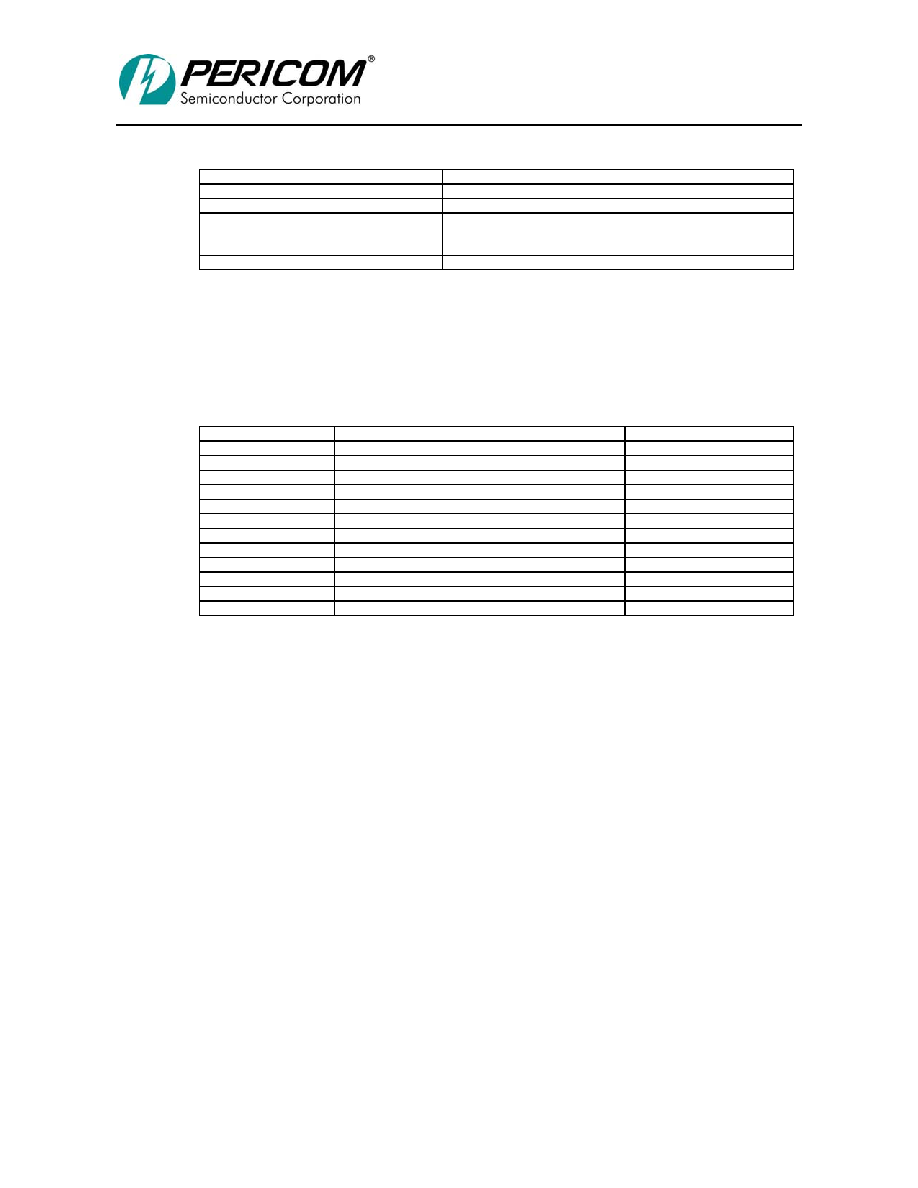
Table 8-1 GPIO OPERATION
GPIO Pin
Operation
GPIO[0]
Shift register clock output at 33MHz max frequency
GPIO[1]
Not used
GPIO[2]
Shift register control
0: Load
1: Shift
GPIO[3]
Not used
The data is input through the dedicated input signal, MSK_IN.
The shift register circuitry is not necessary for correct operation of PI7C8154B. The shift register
can be eliminated, and MSK_IN can be tied LOW to enable all secondary clock outputs or tied
HIGH to force all secondary clock outputs HIGH. Table 8-2 shows the format of the serial stream.
Table 8-2 GPIO SERIAL DATA FORMAT
Bit
Description
S_CLKOUT
[1:0]
Slot 0 PRSNT#[1:0] or device 0
0
[3:2]
Slot 1 PRSNT#[1:0] or device 1
1
[5:4]
Slot 2 PRSNT#[1:0] or device 2
2
[7:6]
Slot 3 PRSNT#[1:0] or device 3
3
[8]
Device 4
4
[9]
Device 5
5
[10]
Device 6
6
[11]
Device 7
7
[12]
Device 8
8
[13]
PI7C8154B S_CLKIN
9
[14]
Reserved
NA
[15]
Reserved
NA
The first 8 bits contain the PRSNT#[1:0] signal values for four slots, and these bits control the
S_CLKOUT[3:0] outputs. If one or both of the PRSNT#[1:0] signals are 0, that indicates that a
card is present in the slot and therefore the secondary clock for that slot is not masked. If these
clocks are connected to devices and not to slots, one or both of the bits should be tied low to enable
the clock.
The next 5 bits are the clock mask for devices; each bit enables or disables the clock for one device.
These bits control the S_CLKOUT[8:4] outputs: 0 enables the clock, and 1 disables the clock.
Bit 13 is the clock enable bit for S_CLKOUT[9], which is connected to PI7C8154B’s S_CLKIN
input.
If desired, the assignment of S_CLKOUT outputs to slots, devices, and PI7C8154B’s S_CLKIN
input can be rearranged from the assignment shown here. However, it is important that the serial
data stream format match the assignment of S_CLKOUT.
The 8 least significant bits are connected to the PRSNT# pins for the slots. The next 5 bits are tied
high to disable their respective secondary clocks because those clocks are not connected to
anything. The next bit is tied LOW because that secondary clock output is connected to the bridge
S_CLKIN input. When the secondary reset signal, S_RESET#, is detected asserted and the primary
reset signal, P_RESET#, is detected deasserted, the bridge drives GPIO[2] LOW for one cycle to
load the clock mask inputs into the shift register. On the next cycle, PI7C8154B drives GPIO[2]
HIGH to perform a shift operation. This shifts the clock mask into MSK_IN; the most significant
bit is shifted in first, and the least significant bit is shifted in last.
相關(guān)PDF資料 |
PDF描述 |
|---|---|
| ADM1025AARQ | IC MONITOR SYS/VOLT 5CH 16QSOP |
| ADUC832BCPZ | IC MCU 62K FLASH ADC/DAC 56LFCSP |
| 31-10 | BNC FRONT MOUNT RECEPT |
| D38999/20JD97SN | CONN RCPT 12POS WALL MNT W/SCKT |
| ADUC848BSZ62-5 | IC FLASH MCU W/16BIT ADC 52MQFP |
相關(guān)代理商/技術(shù)參數(shù) |
參數(shù)描述 |
|---|---|
| PI7C8154BNAE-80 | 功能描述:外圍驅(qū)動器與原件 - PCI 64B/66MHz 2 Port PCI Bridge RoHS:否 制造商:PLX Technology 工作電源電壓: 最大工作溫度: 安裝風(fēng)格:SMD/SMT 封裝 / 箱體:FCBGA-1156 封裝:Tray |
| PI7C8154BNAI | 制造商:Pericom Semiconductor Corporation 功能描述: |
| PI7C8154BNAIE | 功能描述:外圍驅(qū)動器與原件 - PCI 64B/66MHz 2 Port PCI Bridge RoHS:否 制造商:PLX Technology 工作電源電壓: 最大工作溫度: 安裝風(fēng)格:SMD/SMT 封裝 / 箱體:FCBGA-1156 封裝:Tray |
| PI7C8154EVB | 功能描述:界面開發(fā)工具 64B/66MHz 2 Port PCI Bridge Eval Brd RoHS:否 制造商:Bourns 產(chǎn)品:Evaluation Boards 類型:RS-485 工具用于評估:ADM3485E 接口類型:RS-485 工作電源電壓:3.3 V |
| PI7C8154NA-33 | 制造商:PERICOM 功能描述: |
發(fā)布緊急采購,3分鐘左右您將得到回復(fù)。