- 您現(xiàn)在的位置:買賣IC網(wǎng) > PDF目錄69052 > PKL4316APITO (ERICSSON POWER MODULES AB) 1-OUTPUT 366 W DC-DC REG PWR SUPPLY MODULE PDF資料下載
參數(shù)資料
| 型號: | PKL4316APITO |
| 廠商: | ERICSSON POWER MODULES AB |
| 元件分類: | 電源模塊 |
| 英文描述: | 1-OUTPUT 366 W DC-DC REG PWR SUPPLY MODULE |
| 封裝: | 61.50 X 61 MM, 12.70 MM HEIGHT, HALF BRICK PACKAGE-11 |
| 文件頁數(shù): | 5/15頁 |
| 文件大小: | 226K |
| 代理商: | PKL4316APITO |
13
PKL 4316 Series
EN/LZT 146 039 R1A Ericsson Power Modules, November 2003
Thermal Consideration
General
The PKL 4316 Series DC/DC converters are designed to
operate in a variety of thermal environments, however
sufficient cooling should be provided to help ensure reliable
operation. Heat is removed by conduction, convection and
radiation to the surrounding environment. Increased airflow
enhances the heat transfer via convection. The available load
current vs. ambient air temperature and airflow at Vin=53 V
for each model is according to the information given under
the output section. The test is done in a wind tunnel with a
cross section of 305x305mm, the DC/DC converter vertically
mounted on a 6 layer PCB with a size of 254x254mm. Proper
cooling can be verified by measuring the temperature of
selected devices.
Calculation of ambient temperature
By using the thermal resistance the maximum allowed
ambient temperature can be calculated.
1. The powerloss is calculated by using the formula
((1/
η) - 1) × output power = power losses.
η = efciency of converter. E.g 85% = 0.85
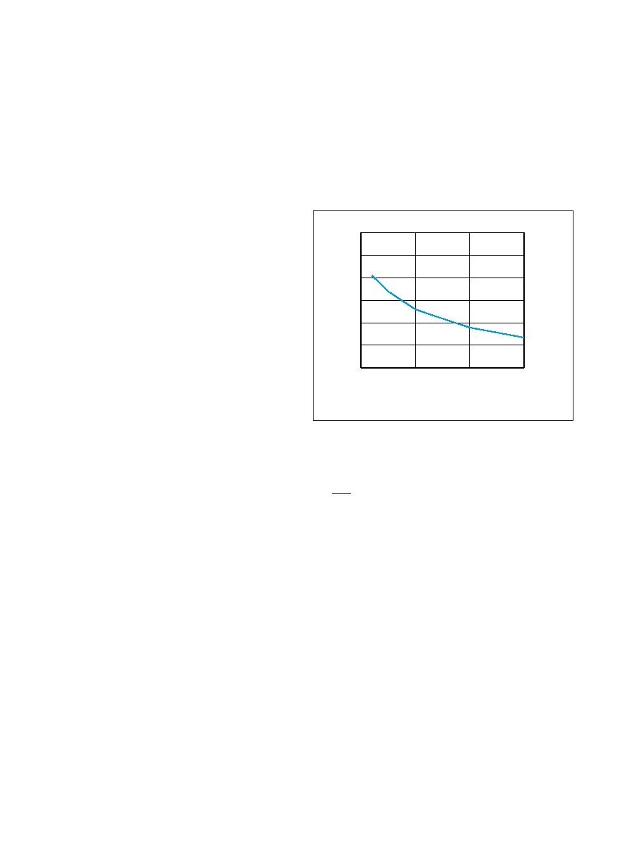
2. Find the value of the thermal resistance in the diagram
by using the airow speed at the module. Take the thermal
resistance x powerloss to get the temperature increase.
Thermal resistance vs. airspeed measured at the converter.
Tested in windtunnel with a cross section of 305×305 mm
mounted on a 6 layer PCB with a size of 254×254 mm.
3. Max allowed calculated ambient temperature is: Max
TC of DC/DC converter – temperature increase.
E.g PKJ 4316 PIT at 2m/s:
B. 34.55W × 1.79°C/W = 61.84°C
C.110°C - 61.84°C = max ambient temperature is 48.16°C
The real temperature will be dependent on several factors,
like PCB size and type, direction of airow, air turbulence
etc. It is recommended to verify the temperature by testing.
A. ((
) - 1) × 311W = 34.55W
1
0.90
0123
0
1
2
3
4
5
6
[m/s]
[°C/W]
相關PDF資料 |
PDF描述 |
|---|---|
| PKL4316APITLA | 1-OUTPUT 366 W DC-DC REG PWR SUPPLY MODULE |
| PKL4316PITLA | 1-OUTPUT 310 W DC-DC REG PWR SUPPLY MODULE |
| PKL4316APITP | 1-OUTPUT 366 W DC-DC REG PWR SUPPLY MODULE |
| PKL4316PITP | 1-OUTPUT 310 W DC-DC REG PWR SUPPLY MODULE |
| PKL4316PITLB | 1-OUTPUT 310 W DC-DC REG PWR SUPPLY MODULE |
相關代理商/技術參數(shù) |
參數(shù)描述 |
|---|---|
| PKL4316PIT | 制造商:Ericsson 功能描述:DC/DC PS SGL-OUT 28V 11A 310W - Bulk |
| PKL4316PITM | 制造商:Ericsson 功能描述:DC/DC PS SGL-OUT 28V 11A 310W - Bulk |
| PKL46-1 | 制造商:Thomas & Betts 功能描述:Pin Terminal (2/0)AWG M 152.4mm Tin |
| PKL4918PIOA | 制造商:Ericsson 功能描述:EXTENDED 1/2 BRICK "DOUBLE P" SERIES, THRU-HOLE, CONVERTER - Bulk |
| PKL4918PIT | 制造商:Ericsson 功能描述:DC/DC PS SGL-OUT 1.8V 50A 90W - Bulk |
發(fā)布緊急采購,3分鐘左右您將得到回復。