- 您現(xiàn)在的位置:買賣IC網(wǎng) > PDF目錄368058 > PM150CVA120 (Mitsubishi Electric Corporation) FLAT-BASE TYPE INSULATED PACKAGE PDF資料下載
參數(shù)資料
| 型號: | PM150CVA120 |
| 廠商: | Mitsubishi Electric Corporation |
| 英文描述: | FLAT-BASE TYPE INSULATED PACKAGE |
| 中文描述: | 平性基地型絕緣包裝 |
| 文件頁數(shù): | 3/6頁 |
| 文件大小: | 136K |
| 代理商: | PM150CVA120 |
MITSUBISHI <INTELLIGENT POWER MODULES>
PM150RSE060
FLAT-BASE TYPE
INSULATED PACKAGE
Sep. 2001
TOTAL SYSTEM
P
B
P
N
W
V
U
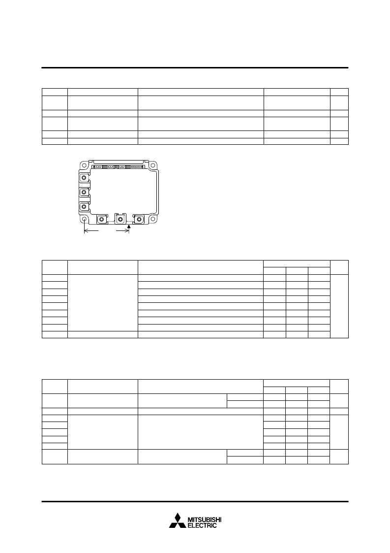
Tc
67mm
Parameter
Symbol
Supply Voltage Protected by
OC & SC
Supply Voltage (Surge)
Module Case Operating
Temperature
Storage Temperature
Isolation Voltage
Condition
V
CC(surge)
T
C
T
stg
V
iso
Ratings
V
CC(PROT)
400
500
–
20 ~ +100
–
40 ~ +125
2500
Unit
V
°
C
°
C
V
rms
V
V
D
= 13.5 ~ 16.5V, Inverter Part,
T
j
= 125
°
C Start
Applied between : P-N, Surge value or without switching
(Note-1)
60Hz, Sinusoidal, Charged part to Base, AC 1 min.
(Note-1) Tc measurement point is as shown below. (Base plate depth 3mm)
2.3
2.3
3.3
2.4
0.3
1.0
3.3
1.2
1
10
Min.
—
—
—
0.8
—
—
—
—
—
—
Typ.
1.7
1.7
2.2
1.2
0.15
0.4
2.4
0.6
—
—
Max.
Collector-Emitter
Saturation Voltage
FWDi Forward Voltage
Collector-Emitter
Cutoff Current
–
I
C
= 150A, V
D
= 15V, V
CIN
= 15V
(Fig. 2)
T
j
= 25
°
C
T
j
= 125
°
C
ELECTRICAL CHARACTERISTICS
(Tj = 25
°
C, unless otherwise noted)
INVERTER PART
Parameter
Symbol
Test Condition
V
CE(sat)
I
CES
V
EC
t
on
t
rr
t
c(on)
t
off
t
c(off)
Limits
T
j
= 25
°
C
T
j
= 125
°
C
Switching Time
V
D
= 15V, V
CIN
= 15V
0V
V
CC
= 300V, I
C
= 150A
T
j
= 125
°
C
Inductive Load (upper and lower arm)
(Fig. 3)
V
CE
= V
CES
, V
CIN
= 15V
(Fig. 4)
V
D
= 15V, I
C
= 150A
V
CIN
= 0V, Pulsed
(Fig. 1)
V
mA
V
μ
s
Unit
°
C/W
R
th(j-c)Q
R
th(j-c)F
R
th(j-c)Q
R
th(j-c)F
R
th(j-c
’
)Q
R
th(j-c
’
)F
R
th(j-c
’
)Q
R
th(j-c
’
)F
R
th(c-f)
(Note-2) T
C
measurement point is just under the chips.
If you use this value, R
th(f-a)
should be measured just under the chips.
Symbol
Test Condition
Unit
Limits
Typ.
—
—
—
—
—
—
—
—
—
—
—
—
—
—
—
—
—
—
THERMAL RESISTANCES
Min.
Max.
0.30
0.47
0.51
1.00
0.17
0.27
0.35
0.64
0.027
Inverter IGBT part (per 1 element), (Note-1)
Inverter FWDi part (per 1 element), (Note-1)
Brake IGBT part, (Note-1)
Brake FWDi part, (Note-1)
Inverter IGBT part (per 1 element), (Note-2)
Inverter FWDi part (per 1 element), (Note-2)
Brake IGBT part, (Note-2)
Brake FWDi part, (Note-2)
Case to fin, Thermal grease applied (per 1 module)
Parameter
Junction to case Thermal
Resistances
Contact Thermal Resistance
相關(guān)PDF資料 |
PDF描述 |
|---|---|
| PM150DSA120 | FLAT-BASE TYPE INSULATED PACKAGE |
| PM150CSA060 | FLAT-BASE TYPE INSULATED PACKAGE |
| PM150CSE120 | FLAT-BASE TYPE INSULATED PACKAGE |
| PM150RSA060 | FLAT-BASE TYPE INSULATED PACKAGE |
| PM150CVA060 | FLAT-BASE TYPE INSULATED PACKAGE |
相關(guān)代理商/技術(shù)參數(shù) |
參數(shù)描述 |
|---|---|
| PM150CVA120_05 | 制造商:MITSUBISHI 制造商全稱:Mitsubishi Electric Semiconductor 功能描述:INTELLIGENT POWER MODULES FLAT-BASE TYPE INSULATED PACKAGE |
| PM150CVA120_09 | 制造商:MITSUBISHI 制造商全稱:Mitsubishi Electric Semiconductor 功能描述:FLAT-BASE TYPE INSULATED PACKAGE |
| PM150D12 | 制造商:POWERBOX 制造商全稱:Powerbox 功能描述:120 - 240 WATTS DC/DC SINGLE |
| PM150D13.8 | 制造商:POWERBOX 制造商全稱:Powerbox 功能描述:120 - 240 WATTS DC/DC SINGLE |
| PM150D15 | 制造商:POWERBOX 制造商全稱:Powerbox 功能描述:120 - 240 WATTS DC/DC SINGLE |
發(fā)布緊急采購,3分鐘左右您將得到回復。