- 您現(xiàn)在的位置:買賣IC網(wǎng) > PDF目錄370009 > PM7524 (Analog Devices, Inc.) CMOS 8-Bit Buffered Multiplying DAC PDF資料下載
參數(shù)資料
| 型號: | PM7524 |
| 廠商: | Analog Devices, Inc. |
| 英文描述: | CMOS 8-Bit Buffered Multiplying DAC |
| 中文描述: | 的CMOS 8位緩沖乘法DAC |
| 文件頁數(shù): | 2/8頁 |
| 文件大小: | 175K |
| 代理商: | PM7524 |

REV. B
–2–
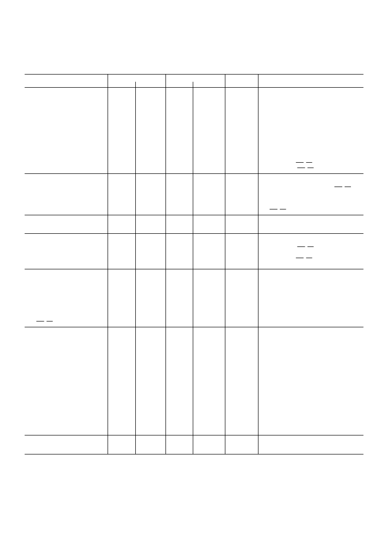
AD7524–SPECIFICATIONS
Limit, T
A
= +25
8
C
V
DD
= +5 V V
DD
= +15 V V
DD
= 5 V
Limit, T
MIN
, T
1
Parameter
DD
= +15 V
Units
T est Conditions/Comments
ST AT IC PERFORMANCE
Resolution
Relative Accuracy
J, A, S Versions
K , B, T Versions
L, C, U Versions
Monotonicity
Gain Error
Average Gain T C
3
8
8
8
8
Bits
±
1/2
±
1/2
±
1/2
Guaranteed Guaranteed
±
2 1/2
±
40
±
1/2
±
1/4
±
1/8
±
1/2
±
1/2
±
1/2
Guaranteed
±
3 1/2
±
40
±
1/2
±
1/4
±
1/8
Guaranteed
±
1 1/2
±
10
LSB max
LSB max
LSB max
±
1 1/4
±
10
LSB max
ppm/
°
C
Gain T C Measured from +25
°
C to
T
MIN
or from +25
°
C to T
MAX
V
DD
=
±
10%
DC Supply Rejection,
3
Gain/
V
DD
0.08
0.002
0.02
0.16
0.01
0.04
0.005
% FSR/% max
% FSR/% typ
Output Leakage Current
I
OUT 1
(Pin 1)
I
OUT 2
(Pin 2)
DYNAMIC PERFORMANCE
Output Current Settling T ime
3
(to 1/2 LSB)
±
50
±
50
±
50
±
50
±
400
±
400
±
200
±
200
nA max
nA max
DB0–DB7 = 0 V;
WR
,
CS
= 0 V; V
REF
=
±
10 V
DB0–DB7 = V
DD
;
WR
,
CS
= 0 V; V
REF
=
±
10 V
400
250
500
350
ns max
OUT 1 Load = 100
, C
EX T
= 13 pF;
WR
,
CS
=
0 V; DB0–DB7 = 0 V to V
DD
to 0 V.
AC Feedthrough
3
at OUT 1
at OUT 2
REFERENCE INPUT
R
IN
(Pin 15 to GND)
4
0.25
0.25
0.25
0.25
0.5
0.5
0.5
0.5
% FSR max
% FSR max
V
=
±
10 V, 100 kHz Sine Wave; DB0–DB7 =
0 V;
WR
,
CS
= 0 V
5
20
5
20
5
20
5
20
k
min
k
max
ANALOG OUT PUT S
Output Capacitance
3
C
OUT 1
(Pin 1)
C
OUT 2
(Pin 2)
C
OUT 1
(Pin 1)
C
OUT 2
(Pin 2)
DIGIT AL INPUT S
Input HIGH Voltage Requirement
V
Input LOW Voltage Requirement
V
Input Current
I
Input Capacitance
3
DB0–DB7
WR
,
CS
SWIT CHING CHARACT ERIST ICS
Chip Select to Write Setup T ime
t
AD7524J, K , L, A, B, C
AD7524S, T , U
Chip Select to Write Hold T ime
t
All Grades
Write Pulse Width
t
AD7524J, K , L, A, B, C
AD7524S, T , U
Data Setup T ime
t
AD7524J, K , L, A, B, C
AD7524S, T , U
Data Hold T ime
t
All Grades
POWER SUPPLY
I
DD
120
30
30
120
120
30
30
120
120
30
30
120
120
30
30
120
pF max
pF max
pF max
pF max
DB0–DB7 = V
DD
;
WR
,
CS
= 0 V
DB0–DB7 = 0 V;
WR
,
CS
= 0 V
+2.4
+13.5
+2.4
+13.5
V min
+0.8
+1.5
+0.5
+1.5
V max
±
1
±
1
±
10
±
10
μ
A max
V
IN
= 0 V or V
DD
5
20
5
20
5
20
5
20
pF max
pF max
V
IN
= 0 V
V
IN
= 0 V
See T iming Diagram
t
WR
= t
CS
170
170
100
100
220
240
130
150
ns min
ns min
0
0
0
0
ns min
t
CS
≥
t
WR
, t
CH
≥
0
170
170
100
100
220
240
130
150
ns min
ns min
135
135
60
60
170
170
80
100
ns min
ns min
10
10
10
10
ns min
1
100
2
100
2
500
2
500
mA max
μ
A max
All Digital Inputs V
or V
IH
All Digital Inputs 0 V or V
DD
NOT ES
1
T emperature ranges as follows: J, K , L versions: –40
°
C to +85
°
C
A, B, C versions: –40
°
C to +85
°
C
S, T , U versions: –55
°
C to +125
°
C
2
Gain error is measured using internal feedback resistor. Full-Scale Range (FSR) = V
REF
.
3
Guaranteed not tested.
4
DAC thin-film resistor temperature coefficient is approximately –300 ppm/
°
C.
5
AC parameter, sample tested @ +25
°
C to ensure conformance to specification.
Specifications subje
ct to change without notice
.
(V
REF
= +10 V, V
OUT1
= V
OUT2
= 0 V, unless otherwse noted)
相關(guān)PDF資料 |
PDF描述 |
|---|---|
| PM7574 | CMOS uP-COMPATIBLE 8-BIT DAC |
| PM75CSAJ120 | Analog IC |
| PM75CSE120 | Controller Miscellaneous - Datasheet Reference |
| PM75DHA120 | TRANSISTOR | IGBT POWER MODULE | HALF BRIDGE | 1.2KV V(BR)CES | 75A I(C) |
| PM75RHA060 | TRANSISTOR | IGBT POWER MODULE | 3-PH BRIDGE | 600V V(BR)CES | 75A I(C) |
相關(guān)代理商/技術(shù)參數(shù) |
參數(shù)描述 |
|---|---|
| PM75240054Q | 制造商:Analog Devices 功能描述: |
| PM7524AQ | 制造商:Rochester Electronics LLC 功能描述:- Bulk 制造商:Analog Devices 功能描述: |
| PM7524BQ/883C | 制造商:Analog Devices 功能描述: |
| PM7524BRC/883 | 制造商:未知廠家 制造商全稱:未知廠家 功能描述:8-Bit Digital-to-Analog Converter |
| PM7524BRC/883C | 制造商:Rochester Electronics LLC 功能描述:- Bulk |
發(fā)布緊急采購,3分鐘左右您將得到回復(fù)。