- 您現(xiàn)在的位置:買賣IC網(wǎng) > PDF目錄69062 > PMB8218HP (ERICSSON POWER MODULES AB) 1-OUTPUT DC-DC REG PWR SUPPLY MODULE PDF資料下載
參數(shù)資料
| 型號: | PMB8218HP |
| 廠商: | ERICSSON POWER MODULES AB |
| 元件分類: | 電源模塊 |
| 英文描述: | 1-OUTPUT DC-DC REG PWR SUPPLY MODULE |
| 封裝: | ROHS COMPLIANT PACKAGE-10 |
| 文件頁數(shù): | 12/32頁 |
| 文件大小: | 1551K |
| 代理商: | PMB8218HP |
第1頁第2頁第3頁第4頁第5頁第6頁第7頁第8頁第9頁第10頁第11頁當前第12頁第13頁第14頁第15頁第16頁第17頁第18頁第19頁第20頁第21頁第22頁第23頁第24頁第25頁第26頁第27頁第28頁第29頁第30頁第31頁第32頁

EN/LZT146066R2A EricssonPowerModules,April2007
PMB8818TPDatasheet
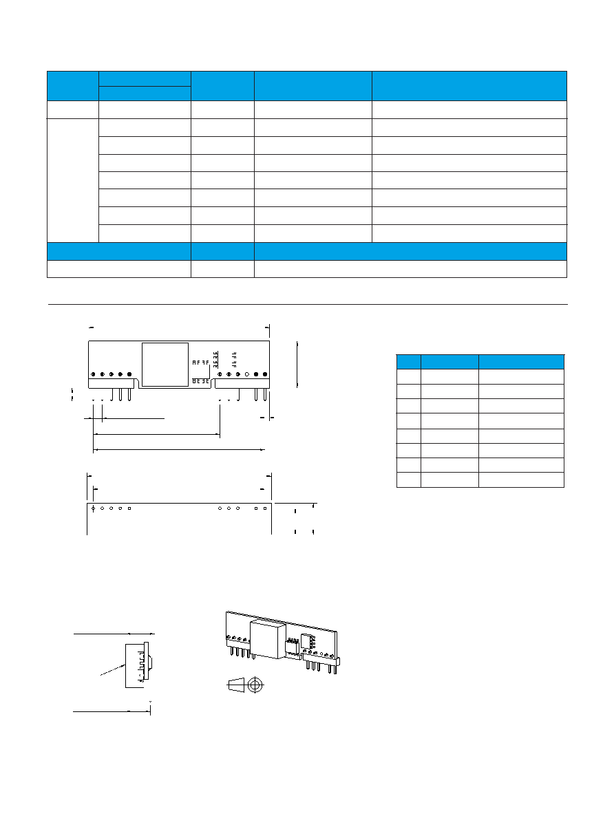
Pin
Designation
Function
1-2
+Out
OutputVoltage
3
+S
Remotesensing
4
+Out
OutputVoltage
5
GND
Ground*
6
GND
Ground*
7-8
+In
InputVoltage
9
Vadj
Outputvoltageadjust
10
RC
Remotecontrol
VI
VO/IOmax
POmax
OrderingNo.
Comment
Output1
8.3-16V
0.75-5.50/16A
80W
PMB8818TP
Released
8.3-16V
1.0V/16A
16W
PMB8118NAP
Onrequest
1.2V/16A
19.2W
PMB8118LAP
Onrequest
1.5V/16A
24W
PMB8218HP
Onrequest
1.8V/16A
28.8W
PMB8218GP
Onrequest
2.5V/16A
40W
PMB8419P
Onrequest
3.3V/16A
52.8W
PMB8510P
Onrequest
5V/16A
80W
PMB8811P
Onrequest
Option
Suffix
Example
NegativeRemoteControllogic
N
PMB8818TPN
8,
80
[0
.3
46
]
7,
40
[0
.2
91
]
51,80 [2.039]
48,26 [1.900]
Recommended footprint (customer board), no components within border.
Holes: 1,0 [0.04] through plated holes with 1,5 [0.06] pads on both sides.
Note 1: For other pin lengths, refer to Product program/Ordering information
1 2 3 4 5
6 7 8
9 10
Dimensions in mm [inch]
Tolerances (unless specified):
x,x +/-0,5 [0.02]
x,xx +/-0,25 [0.01]
E
7,0 [0.27]
8,5 [0.33] max
choke
35,56 [1.400]
48,26 [1.900]
2,54 [0.100] (7x)
(1,27 [0.05])
13
,2
0
[0
.5
20
]
50,8 [2.00]
p
in
le
ng
th
3,
60
[0
.1
42
]
(N
ot
e
1)
1
Connections
Mechanical Data
Weight
7.7g
Pins
Material:Copperalloy
Plating:Mattetinovernickel
Product Program
8,
80
[0
.3
46
]
7,
40
[0
.2
91
]
51,80 [2.039]
48,26 [1.900]
Recommended footprint (customer board), no components within border.
Holes: 1,0 [0.04] through plated holes with 1,5 [0.06] pads on both sides.
Note 1: For other pin lengths, refer to Product program/Ordering information
1 2 3 4 5
6 7 8
9 10
Dimensions in mm [inch]
Tolerances (unless specified):
x,x +/-0,5 [0.02]
x,xx +/-0,25 [0.01]
E
7,0 [0.27]
8,5 [0.33] max
choke
35,56 [1.400]
48,26 [1.900]
2,54 [0.100] (7x)
(1,27 [0.05])
13
,2
0
[0
.5
20
]
50,8 [2.00]
p
in
le
ng
th
3,
60
[0
.1
42
]
(N
ot
e
1)
1
*Shouldbeconnectedtogetherthroughagroundplane.
相關(guān)PDF資料 |
PDF描述 |
|---|---|
| PMB8118NAPN | 1-OUTPUT DC-DC REG PWR SUPPLY MODULE |
| PMC4219WS | 1-OUTPUT 25 W DC-DC REG PWR SUPPLY MODULE |
| PMC4310WSN/C | 1-OUTPUT 33 W DC-DC REG PWR SUPPLY MODULE |
| PMC4118GWS | 1-OUTPUT 18 W DC-DC REG PWR SUPPLY MODULE |
| PMC4118NWS | 1-OUTPUT 10 W DC-DC REG PWR SUPPLY MODULE |
相關(guān)代理商/技術(shù)參數(shù) |
參數(shù)描述 |
|---|---|
| P-MB8516 | 制造商:Panasonic Industrial Company 功能描述:I.C. |
| PMB8518TP | 功能描述:DC/DC轉(zhuǎn)換器 .75-5.5 Vdc 10A Iso Input 8.3-16V 50W RoHS:否 制造商:Murata 產(chǎn)品: 輸出功率: 輸入電壓范圍:3.6 V to 5.5 V 輸入電壓(標稱): 輸出端數(shù)量:1 輸出電壓(通道 1):3.3 V 輸出電流(通道 1):600 mA 輸出電壓(通道 2): 輸出電流(通道 2): 安裝風格:SMD/SMT 封裝 / 箱體尺寸: |
| PMB86 | 制造商:Pentair Technical Products / Hoffman 功能描述:Mobile Base Black, fits 800x500/600mm, Steel |
| P-MB86 | 制造商:Pentair Technical Products / Hoffman 功能描述:Mobile Base |
| PMB8680 | 制造商:INFINEON 制造商全稱:Infineon Technologies AG 功能描述:Dual-Band RF Transceiver for WLAN System Solutions |
發(fā)布緊急采購,3分鐘左右您將得到回復(fù)。