- 您現(xiàn)在的位置:買賣IC網(wǎng) > PDF目錄69064 > PMR8210S/C (ERICSSON POWER MODULES AB) DC-DC REG PWR SUPPLY MODULE PDF資料下載
參數(shù)資料
| 型號(hào): | PMR8210S/C |
| 廠商: | ERICSSON POWER MODULES AB |
| 元件分類: | 電源模塊 |
| 英文描述: | DC-DC REG PWR SUPPLY MODULE |
| 封裝: | 38.61 X 25.91 MM, 9.64 MM HEIGHT, ROHS COMPLIANT, PACKAGE-22 |
| 文件頁(yè)數(shù): | 17/21頁(yè) |
| 文件大小: | 1207K |
| 代理商: | PMR8210S/C |
第1頁(yè)第2頁(yè)第3頁(yè)第4頁(yè)第5頁(yè)第6頁(yè)第7頁(yè)第8頁(yè)第9頁(yè)第10頁(yè)第11頁(yè)第12頁(yè)第13頁(yè)第14頁(yè)第15頁(yè)第16頁(yè)當(dāng)前第17頁(yè)第18頁(yè)第19頁(yè)第20頁(yè)第21頁(yè)

Ericsson Internal
PRODUCT SPECIFICATION
2 (6)
Prepared (also subject responsible if other)
No.
ECOCOLO
2/1301-BMR 629 8210 Uen
Approved
Checked
Date
Rev
Reference
EJANLLI
2009-08-31
B
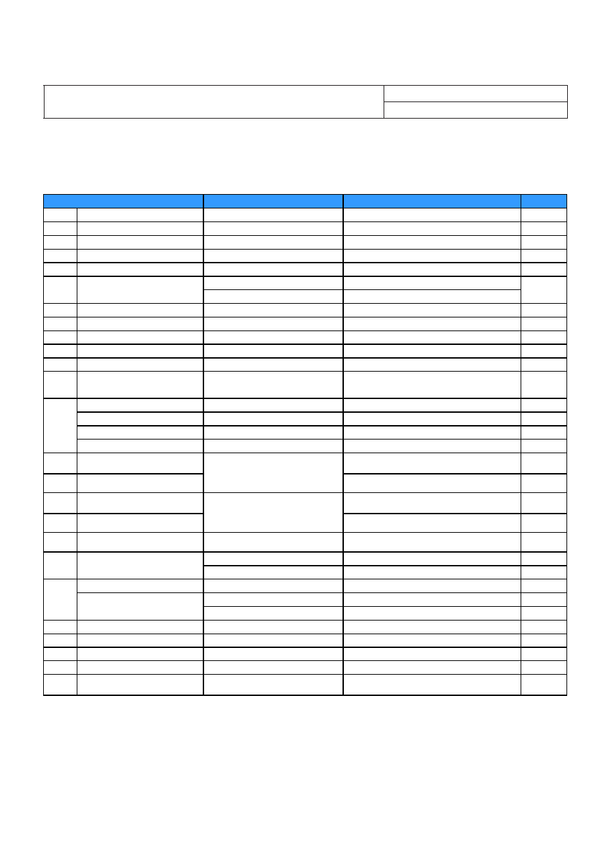
3.3V, 40A / 132W Electrical Specification
PMR 8210
TP1 = -40 to +85C, VI = 8 to 14 V, RSET = 34.0 k, unless otherwise specified under Conditions.
Typical values given at: Tref = +25°C, VI= 12 V, max IO, unless otherwise specified under Conditions.
Additional Cin = 1000+22 F and Cout = 1000 F. See Operating Information section for selection of capacitor types.
Connect the sense pin, where available, to the output pin.
Characteristics
Conditions
min
typ
max
Unit
VI
Input voltage range
8
14
V
VIoff
Turn-off input voltage
Decreasing input voltage
6.7
V
VIon
Turn-on input voltage
Increasing input voltage
7.2
8.0
V
CI
Internal input capacitance
44
μ
F
PO
Output power
0
132
W
50 % of max IO
93.6
η
Efficiency
max IO
93.4
%
Pd
Power Dissipation
max IO
9.5
11.5
W
Pli
Input idling power
IO= 0 A, VI = 12 V
2.0
W
PRC
Input standby power
VI = 12 V (turned off with RC)
0.2
W
IS
Static Input current
VI = 12 V, max IO
11.7
A
fs
Switching frequency
0-100 % of max IO, see Note 1
600
kHz
VOi
Output voltage initial setting and
accuracy
TP1 = +25°C, VI = 12 V, max IO
3.267
3.300
3.333
V
Output voltage tolerance band
0-100 % of max IO
3.25
3.35
V
Idling voltage
IO = 0 A
3.296
3.306
V
Line regulation
max IO
5
10
mV
VO
Load regulation
VI = 12 V, 0-100 % of max IO
5
10
mV
Vtr
Load transient
voltage deviation
±135
mV
ttr
Load transient recovery time
VI = 12 V, Load step 50-100-50 % of
max IO, di/dt = 2.5 A/μs Without
TruboTrans, Cout = 1000 F, Type C
see Note 2
200
μ
s
Vtr
Load transient
voltage deviation
±35
mV
ttr
Load transient recovery time
VI = 12 V, Load step 50-100-50 % of
max IO, di/dt = 2.5 A/μs
With TruboTrans, Cout = 5000 F,
Type C, RTT=SHORT, see Note 2
400
μ
s
ts
Start-up time
(from VI connection to 90 % of VOi)
13.2
ms
max IO
740
μ
s
tf
VI shut-down fall time.
(From VI off to 10 % of VO)
IO =0.4A
50.9
ms
RC start-up time
max IO
12.5
ms
max IO
310
μ
s
{tRC tInh} RC shut-down fall time
(From RC off to 10 % of VO)
Io = 0.4 A
24.5
ms
IO
Output current
0
40
A
Ilim
Current limit threshold
TP1 < max TP1
80
A
Isc
Short circuit current
TP1 = 25C, see Note 3
92
A
Cout
Recommended Capacitive Load
TP1 = 25C, see Note 4
1000
10000
F
VOac
Output ripple & noise
See ripple & noise section,
max IO
20
mVp-p
Note 1: Frequency may be adjusted with SmartSync pin. See Operating Information section
Note 2: See Operating Information section for TurboTrans technology
Note 3: Describe short circuit current characteristic, i.e. fold-back, hiccup or RMS, in one short sentence or type only “See Operating Information section.”)
Note 4: 1000 F of external non-ceramic output capacitance is required for basic operation. Adding additional capacitance at the load further improves transient response. Up to 1000 F of
ceramic capacitance may be added in addition to the required non-ceramic capacitance. When not using TurboTrans technology, 8000 F capacitance is allowed; When using TurboTrans
technology, up to 10000 F capacitance is allowed. For more information, see Operating Information Section.
E
PMR 8000 series
PoL Regulator
Input 8 - 14 V, Output up to 40 A / 210 W
EN/LZT 146 411 R1B November 2009
Ericsson AB
Technical Specication
5
相關(guān)PDF資料 |
PDF描述 |
|---|---|
| PMR8210SR/B | DC-DC REG PWR SUPPLY MODULE |
| PMR8210SR/C | DC-DC REG PWR SUPPLY MODULE |
| PMR8210P/C | DC-DC REG PWR SUPPLY MODULE |
| PMR8210P/B | DC-DC REG PWR SUPPLY MODULE |
| PNP-950-L22 | PLL FREQUENCY SYNTHESIZER, 250 MHz, QCC22 |
相關(guān)代理商/技術(shù)參數(shù) |
參數(shù)描述 |
|---|---|
| PMR8210SR | 功能描述:DC/DC 開關(guān)控制器 PoL Regul in 4.5-14V O/P 0.7-3.6 50A RoHS:否 制造商:Texas Instruments 輸入電壓:6 V to 100 V 開關(guān)頻率: 輸出電壓:1.215 V to 80 V 輸出電流:3.5 A 輸出端數(shù)量:1 最大工作溫度:+ 125 C 安裝風(fēng)格: 封裝 / 箱體:CPAK |
| PMR-9306 | 制造商:BUD 制造商全稱:BUD 功能描述:PANEL MOUNTING RAIL |
| PMR-9448 | 功能描述:機(jī)架和機(jī)柜配件 21" MTG. RAIL SOLD IN PAIRS RoHS:否 制造商:Bivar 產(chǎn)品:Rack Accessories 面板空間: 顏色:Black |
| PMR-9449 | 功能描述:機(jī)架和機(jī)柜配件 31.5" MTG. RAIL SOLD IN PAIRS RoHS:否 制造商:Bivar 產(chǎn)品:Rack Accessories 面板空間: 顏色:Black |
| PMR-9449-NF | 制造商:Bud Industries Inc 功能描述:Panel Mounting Rail |
發(fā)布緊急采購(gòu),3分鐘左右您將得到回復(fù)。