- 您現(xiàn)在的位置:買(mǎi)賣(mài)IC網(wǎng) > PDF目錄69088 > PQ60018ETL45PNS-G (SYNQOR INC) 1-OUTPUT 81 W DC-DC REG PWR SUPPLY MODULE PDF資料下載
參數(shù)資料
| 型號(hào): | PQ60018ETL45PNS-G |
| 廠商: | SYNQOR INC |
| 元件分類(lèi): | 電源模塊 |
| 英文描述: | 1-OUTPUT 81 W DC-DC REG PWR SUPPLY MODULE |
| 封裝: | ROHS COMPLIANT, EIGHTH-BRICK PACKAGE-8 |
| 文件頁(yè)數(shù): | 4/14頁(yè) |
| 文件大?。?/td> | 1098K |
| 代理商: | PQ60018ETL45PNS-G |
第1頁(yè)第2頁(yè)第3頁(yè)當(dāng)前第4頁(yè)第5頁(yè)第6頁(yè)第7頁(yè)第8頁(yè)第9頁(yè)第10頁(yè)第11頁(yè)第12頁(yè)第13頁(yè)第14頁(yè)
Product # PQ60018ETL45
Phone 1-888-567-9596
www.synqor.com
Doc.# 005-2ET618F Rev. B
06/01/09
Page 12
Input:
Output:
Current:
Package:
35-75 V
1.8 V
45 A
Eighth-brick
Technical Specification
APPLICATIONCONSIDERATIONS
Input System Instability: This condition can occur because
any DC/DC converter appears incrementally as a negative
resistance load. A detailed application note titled “Input
SystemInstability”isavailableontheSynQorwebsitewhich
provides an understanding of why this instability arises, and
shows the preferred solution for correcting it.
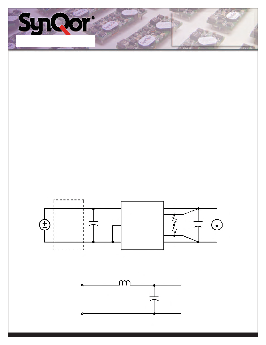
Application Circuits:FigureDbelowprovidesatypicalcircuit
diagram which details the input filtering and voltage trimming.
Input Filtering and External Capacitance:FigureEbelow
provides a diagram showing the internal input filter components.
This filter dramatically reduces input terminal ripple current, which
otherwise could exceed the rating of an external input electro-
lytic capacitor. The recommended external input capacitance is
specified in the “Input Characteristics” section. More detailed
information is available in the application note titled “EMI
Characteristics”ontheSynQorwebsite.
Startup/Restart Inhibit Period: The Restart Inhibit Period
ensures that the converter will remain off for approximately
200msonceitisshutdown.Whenanoutputshortispresent,this
generates a 5Hz “hiccup mode,” which prevents the converter
fromoverheating.Inall,therearefivewaysthattheconvertercan
beshutdownthatinitiateaRestartInhibitPeriod:
InputUnder-VoltageLockout
OutputOver-VoltageProtection
OverTemperatureShutdown
CurrentLimit
TurnedoffbytheON/OFFinput
Figure F shows four turn-on scenarios, where a Restart Inhibit
Period is initiated at t1, t2, and t3:
A Startup Inhibit Period is initiated when the input voltage is
brought up from zero voltage during initial startup, beginning
astheinputvoltagereachesapproximately10V.Attheendof
the Startup Inhibit Period (typically 10mS), if the ON/OFF pin
has been active for at least 1ms, and the input voltage is above
theUnder-VoltageLockoutthreshold,theoutputturnsonwiththe
TypicalTurn-OnTime.Thisisshownattimet0.
Vin
External
Input
Filter
Trim
Vin(+)
Iload
Cload
L
C
Vout(+)
Rtrim-up
or
Rtrim-down
Vsense(+)
ON/OFF
Vin(_)
Vin(+)
Vin(_)
Vout(_)
Vsense(_)
Figure D: Typical application circuit (negative logic unit, permanently enabled).
Figure E: Internal Input Filter Diagram (component values listed on the specifications page).
Electrolytic
Capacitor
47F
相關(guān)PDF資料 |
PDF描述 |
|---|---|
| PQ60018ETL45PYS-G | 1-OUTPUT 81 W DC-DC REG PWR SUPPLY MODULE |
| PQ60018ETL45NNS-G | 1-OUTPUT 81 W DC-DC REG PWR SUPPLY MODULE |
| PQ60018ETL45PKS-G | 1-OUTPUT 81 W DC-DC REG PWR SUPPLY MODULE |
| PQ60018HPA80PKF-G | 1-OUTPUT DC-DC REG PWR SUPPLY MODULE |
| PQ60018HPA80PYF-G | 1-OUTPUT DC-DC REG PWR SUPPLY MODULE |
相關(guān)代理商/技術(shù)參數(shù) |
參數(shù)描述 |
|---|---|
| PQ60018ETL45PRS | 制造商:SYNQOR 制造商全稱(chēng):SYNQOR 功能描述:Eighth-brick DC/DC Converter |
| PQ60018ETL45PYS | 制造商:SYNQOR 制造商全稱(chēng):SYNQOR 功能描述:Eighth-brick DC/DC Converter |
| PQ60018HPA80 | 制造商:SYNQOR 制造商全稱(chēng):SYNQOR 功能描述:Half-brick DC/DC Converter |
| PQ60018HPA80NKF | 制造商:SYNQOR 制造商全稱(chēng):SYNQOR 功能描述:Half-brick DC/DC Converter |
| PQ60018HPA80NKS | 制造商:SYNQOR 制造商全稱(chēng):SYNQOR 功能描述:Half-brick DC/DC Converter |
發(fā)布緊急采購(gòu),3分鐘左右您將得到回復(fù)。