- 您現(xiàn)在的位置:買賣IC網(wǎng) > PDF目錄69104 > PQ60260HTB10NRF (SYNQOR INC) 1-OUTPUT 250 W DC-DC REG PWR SUPPLY MODULE PDF資料下載
參數(shù)資料
| 型號: | PQ60260HTB10NRF |
| 廠商: | SYNQOR INC |
| 元件分類: | 電源模塊 |
| 英文描述: | 1-OUTPUT 250 W DC-DC REG PWR SUPPLY MODULE |
| 封裝: | HALF-BRICK PACKAGE-11 |
| 文件頁數(shù): | 3/13頁 |
| 文件大?。?/td> | 1524K |
| 代理商: | PQ60260HTB10NRF |

Product # PQ60260HTB10
Phone 1-888-567-9596
www.synqor.com
Doc.# 005-2HTB26F Rev. H
10/10/08
Page 11
Input:
Output:
Current:
Package:
35-75 V
26 V
9.6 A (250W)
Half-brick
Technical Specification
APPLICATIONCONSIDERATIONS
Input System Instability: This condition can occur because any
DC/DCconverterappearsincrementallyasanegativeresistanceload.
Adetailedapplicationnotetitled“InputSystemInstability”isavailable
ontheSynQorwebsitewhichprovidesanunderstandingofwhythis
instabilityarises,andshowsthepreferredsolutionforcorrectingit.
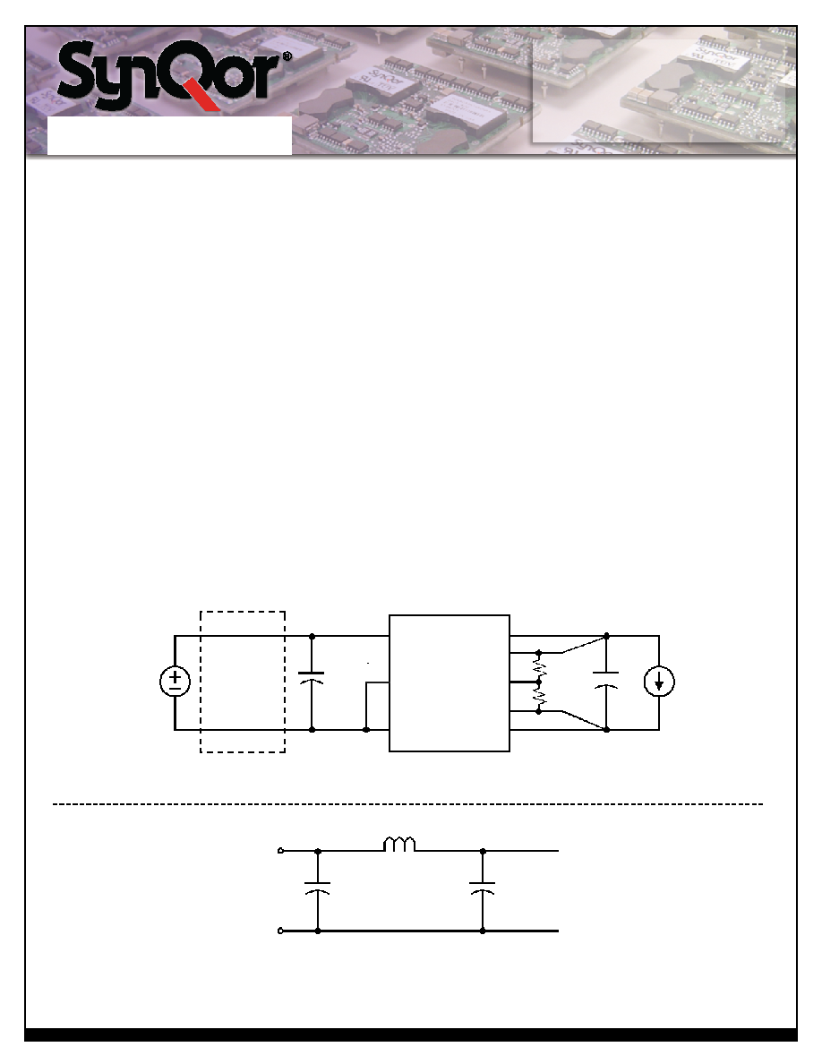
Application Circuits:FigureDbelowprovidesatypicalcircuit
diagramwhichdetailstheinputfilteringandvoltagetrimming.
Input Filtering and External Capacitance: Figure E below
provides a diagram showing the internal input filter components.
Thisfilterdramaticallyreducesinputterminalripplecurrent,which
otherwisecouldexceedtheratingofanexternalelectrolyticinput
capacitor.Therecommendedexternalinputcapacitanceisspecified
intheInputCharacteristicssectionontheElectricalSpecifications
page. More detailed information is available in the application
notetitled“EMICharacteristics”ontheSynQorwebsite.
Startup Inhibit Period:TheStartupInhibitPeriodensuresthat
theconverterwillremainoffforapproximately200mswhenitis
shutdownforanyreason.Whenanoutputshortispresent,this
generatesa5Hz“hiccupmode,”whichpreventstheconverterfrom
overheating.Inall,therearesevenwaysthattheconvertercanbe
shutdown,initiatingaStartupInhibitPeriod:
InputUnder-VoltageLockout
InputOver-VoltageShutdown(notpresentinQuarter-brick)
OutputOver-VoltageProtection
OverTemperatureShutdown
CurrentLimit
ShortCircuitProtection
TurnedoffbytheON/OFFinput
Figure F shows three turn-on scenarios, where a Startup Inhibit
Periodisinitiatedatt0,t1,andt2:
Beforetimet0,whentheinputvoltageisbelowtheUVLthreshold,
the unit is disabled by the Input Under-Voltage Lockout feature.
When the input voltage rises above the UVLthreshold, the Input
Under-VoltageLockoutisreleased,andaStartupInhibitPeriodis
initiated.Attheendofthisdelay,theON/OFFpinisevaluated,
andsinceitisactive,theunitturnson.
Attimet1,theunitisdisabledbytheON/OFFpin,anditcannotbe
enabledagainuntiltheStartupInhibitPeriodhaselapsed.
WhentheON/OFFpingoeshighaftert2,theStartupInhibitPeriod
has elapsed, and the output turns on within the typical Turn-On
Time.
Vin
External
Input
Filter
Trim
Vin(+)
Iload
Cload
C1
L
C2
Vout(+)
Rtrim-up
or
Rtrim-down
Vsense(+)
ON/OFF
Vin(_)
Vin(+)
Vin(_)
Vout(_)
Vsense(_)
Figure D: Typical application circuit (negative logic unit, permanently enabled).
Figure E: Internal Input Filter Diagram (component values listed on page 3).
Electrolytic
Capacitor
47F
相關(guān)PDF資料 |
PDF描述 |
|---|---|
| PQ60260HTB10PNS | 1-OUTPUT 250 W DC-DC REG PWR SUPPLY MODULE |
| PQ60260HTB10NRS | 1-OUTPUT 250 W DC-DC REG PWR SUPPLY MODULE |
| PQ60260HTB10PYS | 1-OUTPUT 250 W DC-DC REG PWR SUPPLY MODULE |
| PQ60260HTB10NYF | 1-OUTPUT 250 W DC-DC REG PWR SUPPLY MODULE |
| PQ60260HTB10NKF | 1-OUTPUT 250 W DC-DC REG PWR SUPPLY MODULE |
相關(guān)代理商/技術(shù)參數(shù) |
參數(shù)描述 |
|---|---|
| PQ60260HTB10NRS | 制造商:SYNQOR 制造商全稱:SYNQOR 功能描述:Half-brick DC/DC Converter |
| PQ60260HTB10NYF | 制造商:SYNQOR 制造商全稱:SYNQOR 功能描述:Half-brick DC/DC Converter |
| PQ60260HTB10NYS | 制造商:SYNQOR 制造商全稱:SYNQOR 功能描述:Half-brick DC/DC Converter |
| PQ60260HTB10PKF | 制造商:SYNQOR 制造商全稱:SYNQOR 功能描述:Half-brick DC/DC Converter |
| PQ60260HTB10PKS | 制造商:SYNQOR 制造商全稱:SYNQOR 功能描述:Half-brick DC/DC Converter |
發(fā)布緊急采購,3分鐘左右您將得到回復。