- 您現(xiàn)在的位置:買賣IC網(wǎng) > PDF目錄69104 > PQ60260HTB10PRS (SYNQOR INC) 1-OUTPUT 250 W DC-DC REG PWR SUPPLY MODULE PDF資料下載
參數(shù)資料
| 型號: | PQ60260HTB10PRS |
| 廠商: | SYNQOR INC |
| 元件分類: | 電源模塊 |
| 英文描述: | 1-OUTPUT 250 W DC-DC REG PWR SUPPLY MODULE |
| 封裝: | HALF-BRICK PACKAGE-11 |
| 文件頁數(shù): | 4/13頁 |
| 文件大小: | 1524K |
| 代理商: | PQ60260HTB10PRS |

Product # PQ60260HTB10
Phone 1-888-567-9596
www.synqor.com
Doc.# 005-2HTB26F Rev. H
10/10/08
Page 12
Input:
Output:
Current:
Package:
35-75 V
26 V
9.6 A (250W)
Half-brick
Technical Specification
FULLFEATUREAPPLICATIONNOTES
This section provides some basic application information for the
full-feature version of the PowerQor series converter. The pin-out
configurationfortheseoptionalfeaturepinsisshownonpage2,
andthepartnumberingformatisshownonthelastpageofthis
specificationsheet.
All units in this product family include back-drive protection to
simplifytheuseofmultipleconvertersinaparallelorsequencing
application. However, any voltage applied to the output of the
convertershouldbekeptbelow120%oftheratedoutputvoltage
oftheconverter.
Inadditiontoback-driveprotection,theseunitsincludethefollow-
ingfeatures(pins):
Current Share (pin 3):Theactivecurrentsharefeatureallows
forN+1andparallelapplications.Toachieveloadsharing,direct-
lyconnecttheIsharepinsofmultipleunits.Theloadcurrentwill
shareequallyamongthemultipleunits(±5%atfullratedcurrent).
ItisimportantthattheVin(-)pinsofthesharingunitsbedirectlycon-
nectedandNOTplacedoutsideofanEMIfilterorotherimpedance
path.ThevoltageattheISharepinwillrangefrom0to5volts(at
fullratedcurrent),referencedtotheprimary-sideground,Vin(-).
Start Sync (pin B):TheStartSynchronizationpinwillallowa
moreconsistentstart-upsequence.Tooperatethisfeature,connect
togethertheStart-Syncpinsofmultiplecurrent-sharingunits.Thiswill
permitimmediatestart-upwithloadsgreaterthanthecurrentlimitof
asingleunit.Withoutthisconnection,anysetofconvertersattempt-
ingtoasynchronouslystart(orre-start)withaloadgreaterthanthe
currentlimitofasingleunitwill“hiccup”.This“hiccup”modewill
continueuntiloneconverterattemptsastartatthesametimeasthe
minimumnumberofadditionalunitsnecessarytosustaintheload
condition.Forexample,three50ampunitsstartingintoa90amp
loadwouldrequiretwounitstosimultaneouslyattemptastart.The
StartSyncconnectionsynchronizesthesestartingattemptsandpro-
videsamoreconsistentandreliablestart-upsequence.Fordetails
aboutthe“hiccupmode”orrepeatedstartupattempts,pleasesee
the“StartupInhibitPeriod”noteinthisTechnicalSpecification.
Clock Sync (pin A): The External Clock Synchronization pin
providestheabilityfortheusertocontroltheEMIsignatureand
synchronize sensitive circuitry to quiet periods in the converter
operation.Withthisoption,theconvertercanbesynchronizedto
an external clock signal whose frequency is greater than that of
the free-running internal clock. However, substantially raising the
converter’sfrequencywillreduceitsefficiency.Therefore,therec-
ommendedfrequencyrangefortheexternalclocksynchronization
signalappliedtothispinwouldbethelowestvaluepossiblewithout
droppingbelowtheminimumfrequencylistedbelow:
340KHzforthe26Vunit
Thefollowingrequirementsshouldalsobemet:
Theexternalclocksignalshouldbereferencedtothe
negativeinputvoltage,Vin(-).
Thehighlevelofthesignalshouldbebetween3.5Vand5.0V.
Thelowlevelshouldbebetween-0.5Vand+1.2V.
Donotapplyaclocksignallowerthanthespecified
frequency.
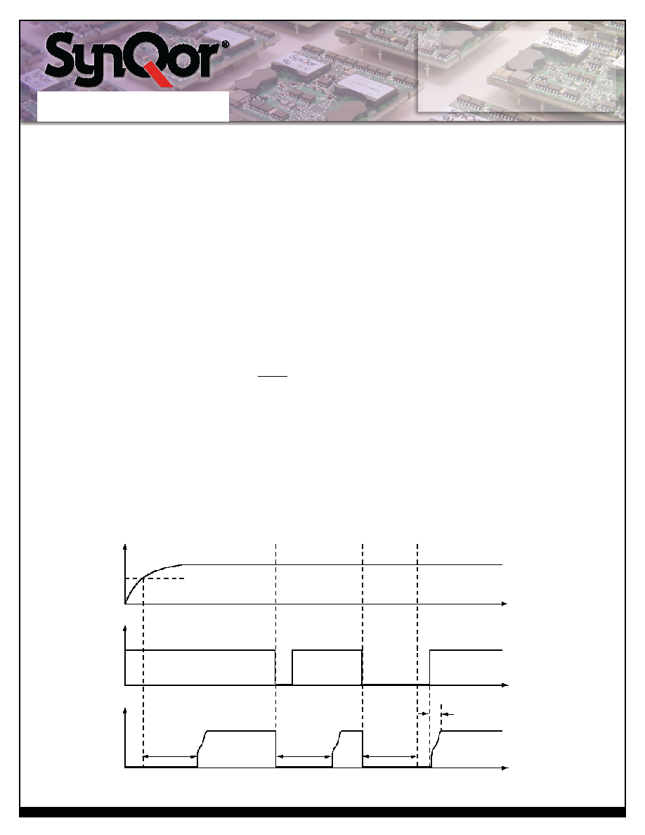
Under-Voltage
LockoutTurn-On
Threshold
ON/OFF
(poslogic)
Figure F: Startup Inhibit Period (turn-on time not
to scale)
Vout
Vin
200ms
(typicalstart-up
inhibitperiod)
t0
t1
t2
t
25ms
(typical
turnontime)
ON
OFF
相關(guān)PDF資料 |
PDF描述 |
|---|---|
| PQ60260HTB10NNS | 1-OUTPUT 250 W DC-DC REG PWR SUPPLY MODULE |
| PQ60260HTB10PKS | 1-OUTPUT 250 W DC-DC REG PWR SUPPLY MODULE |
| PQ60260HTB10PRF | 1-OUTPUT 250 W DC-DC REG PWR SUPPLY MODULE |
| PQ60260HTB10NKS | 1-OUTPUT 250 W DC-DC REG PWR SUPPLY MODULE |
| PQ60280FTF26PKS-G | DC-DC REG PWR SUPPLY MODULE |
相關(guān)代理商/技術(shù)參數(shù) |
參數(shù)描述 |
|---|---|
| PQ60260HTB10PYF | 制造商:SYNQOR 制造商全稱:SYNQOR 功能描述:Half-brick DC/DC Converter |
| PQ60260HTB10PYS | 制造商:SYNQOR 制造商全稱:SYNQOR 功能描述:Half-brick DC/DC Converter |
| PQ60280FTA26 | 制造商:SYNQOR 制造商全稱:SYNQOR 功能描述:Full-brick DC/DC Converter |
| PQ60280FTA26NKF-G | 制造商:SYNQOR 制造商全稱:SYNQOR 功能描述:Full-brick DC/DC Converter |
| PQ60280FTA26NKS-G | 制造商:SYNQOR 制造商全稱:SYNQOR 功能描述:Full-brick DC/DC Converter |
發(fā)布緊急采購,3分鐘左右您將得到回復(fù)。