- 您現(xiàn)在的位置:買賣IC網(wǎng) > PDF目錄368107 > PR02-220K WIDERSTAND LEISTUNG METALL 220K 500V 2W PDF資料下載
參數(shù)資料
| 型號(hào): | PR02-220K |
| 英文描述: | WIDERSTAND LEISTUNG METALL 220K 500V 2W |
| 中文描述: | WIDERSTAND給付220,000 500V 2W的金屬 |
| 文件頁(yè)數(shù): | 2/24頁(yè) |
| 文件大小: | 591K |
| 代理商: | PR02-220K |
第1頁(yè)當(dāng)前第2頁(yè)第3頁(yè)第4頁(yè)第5頁(yè)第6頁(yè)第7頁(yè)第8頁(yè)第9頁(yè)第10頁(yè)第11頁(yè)第12頁(yè)第13頁(yè)第14頁(yè)第15頁(yè)第16頁(yè)第17頁(yè)第18頁(yè)第19頁(yè)第20頁(yè)第21頁(yè)第22頁(yè)第23頁(yè)第24頁(yè)
2001 Jul 13
2
BCcomponents
Product specification
Professional power metal film resistors
PR01/02/03
FEATURES
High power in small packages
Different lead materials for different
applications
Defined interruption behaviour.
APPLICATIONS
All general purpose power
applications.
DESCRIPTION
A homogeneous film of metal alloy is
deposited on a high grade ceramic
body. After a helical groove has been
cut in the resistive layer, tinned
connecting wires of electrolytic copper
or copper-clad iron are welded to the
end-caps. The resistors are coated with
a red, nonflammable lacquer which
provides electrical, mechanical and
climatic protection. This coating is not
resistant to aggressive fluxes. The
encapsulation is resistant to all
cleaning solvents in accordance with
“MIL-STD-202E, method 215”
, and
“IEC 60068-2-45”
.
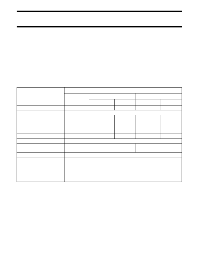
QUICK REFERENCE DATA
Notes
1.
2.
1% tolerance is available for R
n
-range from 1R upwards.
2% tolerance is available on request for R
n
-range from 1R upwards.
DESCRIPTION
VALUE
PR01
PR02
PR03
Cu-lead
FeCu-lead
1
to 1 M
Cu-lead
0.68
to 1 M
FeCu-lead
1
to 1 M
Resistance range
Resistance tolerance and series
Maximum dissipation at
T
amb
= 70
°
C:
R < 1
1
≤
R
Thermal resistance (R
th
)
Temperature coefficient
Maximum permissible voltage
(DC or RMS)
Basic specifications
Climatic category (IEC 60068)
Stability after:
load
climatic tests
soldering
0.22
to 1 M
0.33
to 1 M
±
1% (E24, E96 series);
±
5% (E24 series); see notes 1 and 2
0.6 W
1 W
135 K/W
1.2 W
2 W
75 K/W
1.6 W
3 W
60 K/W
1.3 W
115 K/W
2.5 W
75 K/W
≤±
250
×
10
6
/K
350 V
500 V
750 V
IEC 60115-1 and 60115-4
55/155/56
R/R max.:
±
5% + 0.1
R/R max.:
±
3% + 0.1
R/R max.:
±
1% + 0.05
相關(guān)PDF資料 |
PDF描述 |
|---|---|
| PR02-220R | WIDERSTAND LEISTUNG METALL 220R 500V 2W |
| PR02-22K | WIDERSTAND LEISTUNG METALL 22K 500V 2W |
| PR02-330K | WIDERSTAND LEISTUNG METALL 330K 500V 2W |
| PR1001 | 1 AMP FAST RECOVERY RECTIFIER |
| PR1001 | 1.0A FAST RECOVERY RECTIFIER |
相關(guān)代理商/技術(shù)參數(shù) |
參數(shù)描述 |
|---|---|
| PR02-220R | 制造商:未知廠家 制造商全稱:未知廠家 功能描述:WIDERSTAND LEISTUNG METALL 220R 500V 2W |
| PR02-22K | 制造商:未知廠家 制造商全稱:未知廠家 功能描述:WIDERSTAND LEISTUNG METALL 22K 500V 2W |
發(fā)布緊急采購(gòu),3分鐘左右您將得到回復(fù)。