- 您現(xiàn)在的位置:買(mǎi)賣(mài)IC網(wǎng) > PDF目錄69118 > PSC156-7IRD1 (POWER-ONE INC) 1-OUTPUT DC-DC REG PWR SUPPLY MODULE PDF資料下載
參數(shù)資料
| 型號(hào): | PSC156-7IRD1 |
| 廠商: | POWER-ONE INC |
| 元件分類(lèi): | 電源模塊 |
| 英文描述: | 1-OUTPUT DC-DC REG PWR SUPPLY MODULE |
| 文件頁(yè)數(shù): | 7/13頁(yè) |
| 文件大小: | 223K |
| 代理商: | PSC156-7IRD1 |
第1頁(yè)第2頁(yè)第3頁(yè)第4頁(yè)第5頁(yè)第6頁(yè)當(dāng)前第7頁(yè)第8頁(yè)第9頁(yè)第10頁(yè)第11頁(yè)第12頁(yè)第13頁(yè)

PSC Series Extended Data Sheet
Positive Switching Regulators (Rugged)
REV. MAY 12, 2004
Page 3 of 13
Electrical Input Data
General Conditions:
TA = 25°C, unless TC is specified
Table 2a: Input data
Input
PSC 126
PSC 156
PSC 246
Characteristics
Conditions
min
typ
max
min
typ
max
min
typ
max
Unit
Vi
Operating input voltage 1
Io = 0 - Io nom
18
144
22
144
31
144
VDC
DVio min Min. diff. voltage Vi – Vo
TC min - TC max
67
7
Vi o
Undervoltage lock-out
12
15
19
Ii 0
No load input current
Io = 0, Vi min - Vi max
35
mA
Iinr p
Peak value of inrush current
Vi nom
250
A
tinr r
Rise time
without option L
55
5
s
tinr h
Time to half-value
40
Iinr p
Peak value of inrush current
Vi nom
350
A
tinr r
Rise time
with option L
25
s
tinr h
Time to half-value
125
ui RFI
Input RFI level, EN 55011/22
Vi nom, Io nom
AAA
0.15 - 30 MHz
with option L
B 2
Table 2b: Input data
Input
PSC 366
PSC 486
Characteristics
Conditions
min
typ
max
min
typ
max
Unit
Vi
Operating input voltage 1
Io = 0 - Io nom
44
144
58
144
VDC
DVio min Min. diff. voltage Vi – Vo
TC min - TC max
810
Vi o
Undervoltage lock-out
29
40
Ii 0
No load input current
Io = 0, Vi min - Vi max
40
45
mA
Iinr p
Peak value of inrush current
Vi nom
250
A
tinr r
Rise time
without option L
55
s
tinr h
Time to half-value
40
Iinr p
Peak value of inrush current
Vi nom
350
A
tinr r
Rise time
with option L
25
s
tinr h
Time to half-value
125
ui RFI
Input RFI level, EN 55011/22
Vi nom, Io nom
AA
0.15 - 30 MHz
with option L
B 2
1 Surges up to 156 V for 2 s (complying to LES-DB standard for VBat. = 110 V).
2 With external input capacitor Ce = 470
F/200 V and option L.
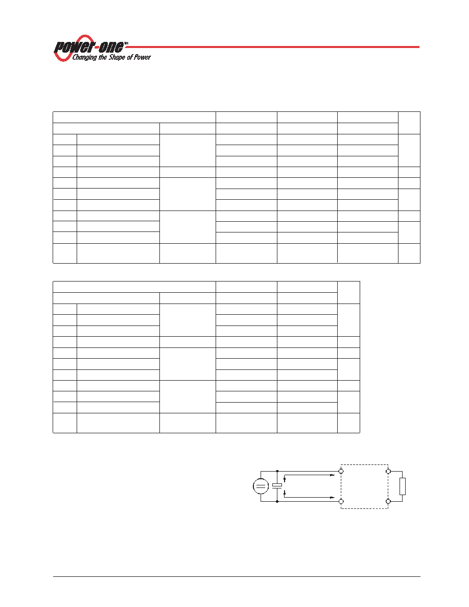
External Input Circuitry
The sum of the lengths of the supply lines to the source or
to the nearest capacitor
≥100 F (a + b) should not exceed
5 m unless option L is fitted. This option is recommended in
order to prevent power line oscillations and reduce super-
imposed interference voltages. See also:
Technical Infor-
mation: Application Notes.
Vi+
Gi–
Vo+
Go–
a
b
+
04016
Fig. 2
Switching regulator with long supply lines.
相關(guān)PDF資料 |
PDF描述 |
|---|---|
| PSC156-9LIRCD1 | 1-OUTPUT DC-DC REG PWR SUPPLY MODULE |
| PSC366-7IRD1 | 1-OUTPUT DC-DC REG PWR SUPPLY MODULE |
| PSC366-7LIR | 1-OUTPUT DC-DC REG PWR SUPPLY MODULE |
| PSC486-7LIPD | 1-OUTPUT DC-DC REG PWR SUPPLY MODULE |
| PSC126-9LIRD | 1-OUTPUT DC-DC REG PWR SUPPLY MODULE |
相關(guān)代理商/技術(shù)參數(shù) |
參數(shù)描述 |
|---|---|
| PSC156-9IR | 制造商:Power-One 功能描述:DC/DC PS SGL-OUT 15V 6A 90W 9PIN - Bulk |
| PSC158-7IR | 功能描述:SWITCHING REGULATOR 120W 15V RoHS:是 類(lèi)別:電源 - 板載 >> DC DC Converters 系列:* 標(biāo)準(zhǔn)包裝:5 系列:* |
| PSC158-9IR | 制造商:Power-One 功能描述:DC/DC PS SGL-OUT 15V 8A 120W 9PIN - Bulk |
| PSC159-2 | 功能描述:SWITCHING REGULATOR 135W 15V RoHS:是 類(lèi)別:電源 - 板載 >> DC DC Converters 系列:* 標(biāo)準(zhǔn)包裝:5 系列:* |
| PSC159-2IR | 制造商:Power-One 功能描述: |
發(fā)布緊急采購(gòu),3分鐘左右您將得到回復(fù)。