- 您現(xiàn)在的位置:買賣IC網(wǎng) > PDF目錄69119 > PSC156-9LIPD1 (POWER-ONE INC) 1-OUTPUT DC-DC REG PWR SUPPLY MODULE PDF資料下載
參數(shù)資料
| 型號: | PSC156-9LIPD1 |
| 廠商: | POWER-ONE INC |
| 元件分類: | 電源模塊 |
| 英文描述: | 1-OUTPUT DC-DC REG PWR SUPPLY MODULE |
| 文件頁數(shù): | 13/13頁 |
| 文件大?。?/td> | 223K |
| 代理商: | PSC156-9LIPD1 |

PSC Series Extended Data Sheet
Positive Switching Regulators (Rugged)
REV. MAY 12, 2004
Page 9 of 13
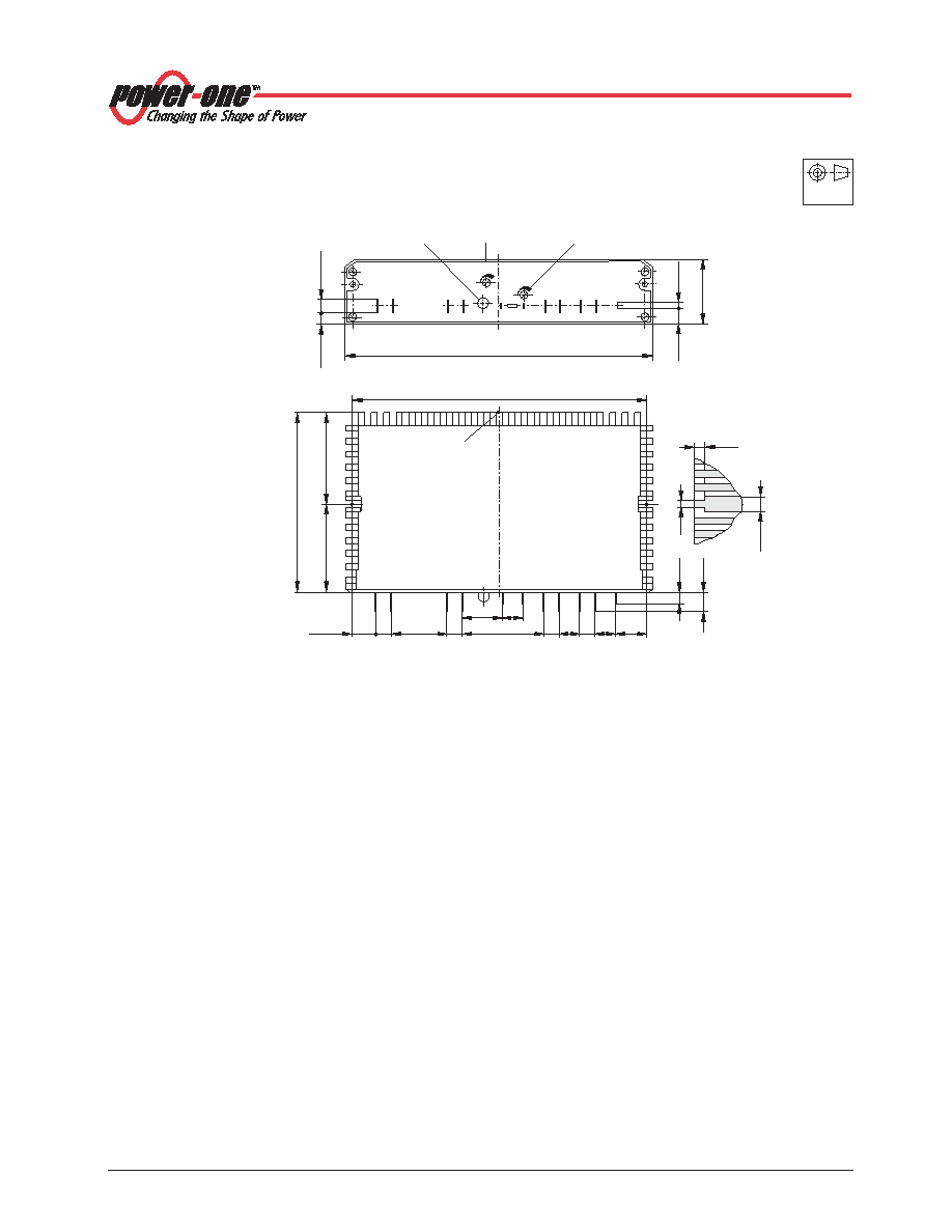
Mechanical Data
Dimensions in mm. Tolerances ±0.3 mm unless otherwise specified.
Gi–
Go–
Vo+
i
Vi+
D
Uo
Ut
GR
7.5
27.5
18.5 11.3
40
7.5 10 7.5 10 (14)
7.5
10
±2
4.3
min.
8
5 ±0.5
144
12.5 ±1
43
±1
(45)
88
±1
7
±2
151 ±1
32.2
±0.5
2.8
x
0.8
8.1
±1
6.35
±1
6.3
x
0.8
Distance between M4 mounting screws
Measuring point
of case temperature
TC
Yellow LED output
voltage indicator
Potentiometer
(option P)
Potentiometer
(option D)
09023
Uo
Fig. 12
Case C02, weight 440 g
Aluminium, black finish and
self cooling
European
Projection
Standards and Approvals
All switching regulators are UL recognized according to UL
1950, UL 1012 and EN 60950, UL recognized for Canada to
CAN/CSA C22.2 No. 234-M90.
The units have been evaluated for:
Building in,
Operational insulation from input to output and input/out-
put to case,
The use in an overvoltage category II environment,
The use in a pollution degree 2 environment.
The switching regulators are subject to manufacturing sur-
veillance in accordance with the above mentioned UL and
CSA and with ISO 9001 standards.
Isolation
Electric strength test voltage between input interconnected
with output against case: 1500 VDC, 1 s.
This test is performed in the factory as routine test in
accordance with EN50116, IEC/EN 60950 and UL 1950
and should not be repeated in the field. Power-One will not
honour any guarantee claims resulting from electric
strength field tests.
Safety and Installation Instructions
Installation Instruction
Installation of the switching regulators must strictly follow
the national safety regulations in compliance with the enclo-
sure, mounting, creepage, clearance, casualty, markings
and segregation requirements of the end-use application.
Check for hazardous voltages before altering any connec-
tions. Connections can be made using fast-on or soldering
technique.
The input and the output circuit are not separated, i.e. the
negative path is internally interconnected!
The units should be connected to a secondary circuit.
Do not open the module.
Ensure that a unit failure (e.g. by an internal short-circuit)
does not result in a hazardous condition. See also:
Safety
of operator accessible output circuit.
Cleaning Agents
In order to avoid possible damage, any penetration of
cleaning fluids is to be prevented, since the power supplies
are not hermetically sealed.
Protection Degree
The protection degree is IP 20.
相關PDF資料 |
PDF描述 |
|---|---|
| PSC246-7IRC | 1-OUTPUT DC-DC REG PWR SUPPLY MODULE |
| PSC246-9IRCD1 | 1-OUTPUT DC-DC REG PWR SUPPLY MODULE |
| PSC486-9LIPCD | 1-OUTPUT DC-DC REG PWR SUPPLY MODULE |
| PSC126-7IPD1 | 1-OUTPUT DC-DC REG PWR SUPPLY MODULE |
| PSC246-7IPCD | 1-OUTPUT DC-DC REG PWR SUPPLY MODULE |
相關代理商/技術參數(shù) |
參數(shù)描述 |
|---|---|
| PSC158-7IR | 功能描述:SWITCHING REGULATOR 120W 15V RoHS:是 類別:電源 - 板載 >> DC DC Converters 系列:* 標準包裝:5 系列:* |
| PSC158-9IR | 制造商:Power-One 功能描述:DC/DC PS SGL-OUT 15V 8A 120W 9PIN - Bulk |
| PSC159-2 | 功能描述:SWITCHING REGULATOR 135W 15V RoHS:是 類別:電源 - 板載 >> DC DC Converters 系列:* 標準包裝:5 系列:* |
| PSC159-2IR | 制造商:Power-One 功能描述: |
| PSC-15A-050 | 功能描述:插入式交流適配器 U 552-PSC-15A-050S 15W 5VDC WALL ADAPT RoHS:否 制造商:Phihong 地區(qū):Universal 安裝風格:Wall, Interchangeable Plug 輸入電壓范圍:90 VAC to 264 VAC 輸出端數(shù)量:1 輸出功率額定值:5 W 輸出電壓(通道 1):5 V 輸出電流(通道 1):1 A 直流輸出連接器:USB Type A 隨附/必需的交流插頭:Required 商用/醫(yī)用:Commercial 效率:Level V |
發(fā)布緊急采購,3分鐘左右您將得到回復。