- 您現(xiàn)在的位置:買賣IC網(wǎng) > PDF目錄69122 > PSC368-9IP (POWER-ONE INC) 1-OUTPUT DC-DC REG PWR SUPPLY MODULE PDF資料下載
參數(shù)資料
| 型號(hào): | PSC368-9IP |
| 廠商: | POWER-ONE INC |
| 元件分類: | 電源模塊 |
| 英文描述: | 1-OUTPUT DC-DC REG PWR SUPPLY MODULE |
| 文件頁(yè)數(shù): | 3/13頁(yè) |
| 文件大小: | 223K |
| 代理商: | PSC368-9IP |
第1頁(yè)第2頁(yè)當(dāng)前第3頁(yè)第4頁(yè)第5頁(yè)第6頁(yè)第7頁(yè)第8頁(yè)第9頁(yè)第10頁(yè)第11頁(yè)第12頁(yè)第13頁(yè)

PSC Series Extended Data Sheet
Positive Switching Regulators (Industrial)
REV. MAY 12, 2004
Page 11 of 13
Description of Options
-9
Extended Temperature Range
The operational ambient temperature range is extended to
TA = –40 to 71°C. (TC = –40 to 95°C, TS = –55 to 100°C.)
P
Potentiometer
Option P excludes R function. The output voltage
Vo can be
adjusted with a screwdriver in the range from 0.92 - 1.08 of
the nominal output voltage
Vo nom.
However, the minimum differential voltage
DVio min between
input and output voltages as specified in:
Electrical Input
Data should be maintained.
L
Input Filter
Option L is recommended to reduce superimposed inter-
ference voltages and to prevent oscillations, if input lines
exceed approx. 5 m in total length. The fundamental wave
(approx. 120 kHz) of the reduced interference voltage be-
tween Vi+ and Gi– has, with an input line inductance of
5 H, a maximum magnitude of 4 mVAC. A reduction can
be achieved by insertion of a capacitor across the input
(e.g. plastic foil between Vi+ and Gi–).
The input impedance of the switching regulator at 120 kHz
is about 3.5
.The harmonics are small in comparison with
the fundamental wave. See also:
Electrical Input Data: RFI.
C
Crowbar
This option is recommended to protect the load against
power supply malfunction, but it is not designed to sink ex-
ternal currents.
A fixed-value monitoring circuit checks the output voltage
Vo. When the trigger voltage Vo c is reached, the thyristor
crowbar triggers and disables the output. It may be deacti-
vated by removal of the input voltage. In case of a switching
transistor defect, an internal fuse prevents excessive cur-
rent.
Note: As a central overvoltage protection device, the crow-
bar is usually connected to the external load via distributed
inductance of the lines. For this reason, the overvoltage at
the load can temporarily exceed the trigger voltage
Voc. De-
pending on the application, further decentralized over-
voltage protection elements may have to be used addition-
ally.
With option L, the maximum permissible additionally su-
perimposed ripple
ui of the input voltage (rectifier mode) at
a specified input frequency
f i has the following values:
Units with max input voltage 40 V:
ui max = 12 Vpp at 100 Hz or Vpp = 1200 Hz/f i 1V
Units with max input voltage 80 V:
ui max pp at 100 Hz or Vpp = 2200 Hz/f i 1V
D
Save Data Input Undervoltage Monitor
Note: Output instead of input undervoltage monitor is
available on request (Option D1).
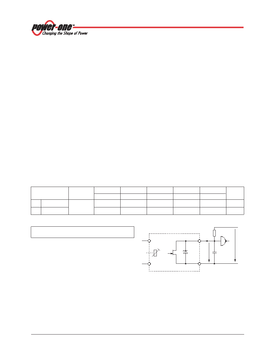
Terminal D and Go– are connected to a normally conduct-
ing field effect transistor (JFET). The switching characteris-
tics of the option D output are shown in fig. Definition of
Vt
and
VH. A 0.5 W Zener diode provides protection against
overvoltages.
The voltage
Vt can be externally adjusted with a trim poten-
tiometer by means of a screwdriver. The hysteresis
VH of Vt
is <2 %. Terminal D stays low for a minimum time
tlow min, in
order to prevent any oscillation.
Vt can be set to a value
between
Vi min and Vi max. Please note that the JFET be-
comes conductive when
VD increases above 7 V approx.
Fig. 13
Test circuit with definition of voltage VD and current ID
Vi +
Gi –
Go –
8.2 V
D
VD
+5 V
100 pF
ID
10 k
JFET
Vt
11025
Table 10: Crowbar trigger levels
Characteristics
Conditions
5.1 V
12 V
15 V
24 V
36 V
Unit
min
max
min
max
min
max
min
max
min
max
Vo c
Trigger voltage
Vi min - Vi max
5.8
6.8
13.5
16
16.5
19
27
31
40
45.5
V
Io = 0 - Io nom
t s
Delay time
TC min - TC max
1.5
s
相關(guān)PDF資料 |
PDF描述 |
|---|---|
| PSC5A12-9IRC | 1-OUTPUT DC-DC REG PWR SUPPLY MODULE |
| PSC5A12-9IR | 1-OUTPUT DC-DC REG PWR SUPPLY MODULE |
| PSC5A12-9LIPCD1 | 1-OUTPUT DC-DC REG PWR SUPPLY MODULE |
| PSC248-7IRD1 | 1-OUTPUT DC-DC REG PWR SUPPLY MODULE |
| PSC248-9IRC | 1-OUTPUT DC-DC REG PWR SUPPLY MODULE |
相關(guān)代理商/技術(shù)參數(shù) |
參數(shù)描述 |
|---|---|
| PSC-368-9-IR | 功能描述:DC/DC轉(zhuǎn)換器 36VDC 8Aout, 288W RoHS:否 制造商:Murata 產(chǎn)品: 輸出功率: 輸入電壓范圍:3.6 V to 5.5 V 輸入電壓(標(biāo)稱): 輸出端數(shù)量:1 輸出電壓(通道 1):3.3 V 輸出電流(通道 1):600 mA 輸出電壓(通道 2): 輸出電流(通道 2): 安裝風(fēng)格:SMD/SMT 封裝 / 箱體尺寸: |
| PSC368-9IR | 制造商:Power-One 功能描述:DC/DC PS SGL-OUT 36V 8A 288W 9PIN - Bulk |
| PS-C-375-BK | 制造商:Brady Corporation 功能描述:0.645 IN W X 75 FT H (W 16.380 MM W X 22.86 M H) |
| PSC39-21EWA | 功能描述:LED 顯示器和配件 AlphaNum Red 625nm Common Cathode RoHS:否 制造商:Avago Technologies 顯示器類型:7 Segment 數(shù)位數(shù)量:2 字符大小:7.8 mm x 14.22 mm 照明顏色:Red 波長(zhǎng):628 nm 共用管腳:Common Anode 工作電壓:2.05 V 工作電流:20 mA 最大工作溫度:+ 85 C 最小工作溫度:- 35 C 封裝:Tube |
| PSC39-21GWA | 功能描述:LED 顯示器和配件 AlphaNum Grn 568nm Common Cathode RoHS:否 制造商:Avago Technologies 顯示器類型:7 Segment 數(shù)位數(shù)量:2 字符大小:7.8 mm x 14.22 mm 照明顏色:Red 波長(zhǎng):628 nm 共用管腳:Common Anode 工作電壓:2.05 V 工作電流:20 mA 最大工作溫度:+ 85 C 最小工作溫度:- 35 C 封裝:Tube |
發(fā)布緊急采購(gòu),3分鐘左右您將得到回復(fù)。