- 您現(xiàn)在的位置:買賣IC網(wǎng) > PDF目錄65987 > PSC3E12-2R (POWER-ONE INC) 1-OUTPUT DC-DC REG PWR SUPPLY MODULE PDF資料下載
參數(shù)資料
| 型號: | PSC3E12-2R |
| 廠商: | POWER-ONE INC |
| 元件分類: | 電源模塊 |
| 英文描述: | 1-OUTPUT DC-DC REG PWR SUPPLY MODULE |
| 文件頁數(shù): | 5/8頁 |
| 文件大小: | 363K |
| 代理商: | PSC3E12-2R |
Benign Environment
Switching Regulators, PCB & Chassis
PSC Series
Edition 4/4.99
5/8
MELCHER
The Power Partners.
Thermal Considerations
When a switching regulator is located in free, quasi-station-
ary air (convection cooling) at a temperature
TA = 50
°C and
is operated at its nominal output current
Io nom, the case
temperature
TC will be about 80
°C after the warm-up
phase, measured at the
Measuring point of case tempera-
ture TC (see: Mechanical Data).
Under practical operating conditions, the ambient tempera-
ture
TA may exceed 50
°C, provided additional measures
(heat sink, fan, etc.) are taken to ensure that the case tem-
perature
TC does not exceed its maximum value of 80
°C.
Example: Sufficient forced cooling allows
TA max = 65
°C. A
simple check of the case temperature
TC (TC
≤80°C) at full
load ensures correct operation of the system.
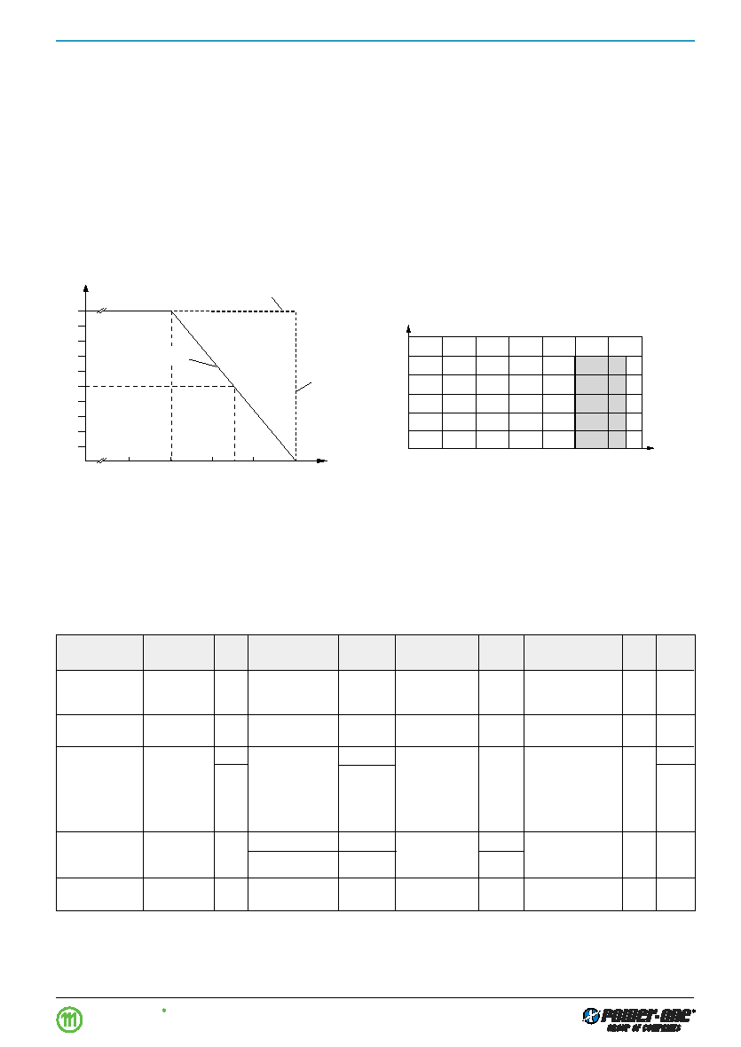
1.2
1.0
0.8
0.6
0.4
0
0.2
0.4
1.0
1.2
0.2
0.6
0.8
1.4
Uo/Uo nom
Io/Io nom
I o
nom
Io L
05033
Fig. 5
Overload, short-circuit behaviour Uo versus Io.
0
0.1
0.2
0.3
0.4
0.5
0.6
0.7
0.8
40
60
70
80
Io/Io nom
TA [°C]
0.9
1.0
Forced cooling
05032
TC max
50
Convection cooling
TA min
Output Protection
A voltage suppressor diode which in worst case conditions
fails into a short circuit, protects the output against an inter-
nally generated overvoltage. Such an overvoltage could
occur due to a failure of either the control circuit or the
switching transistor. The output protection is not designed
to withstand externally applied overvoltages. The user
should ensure that systems with Melcher power supplies, in
the event of a failure, do not result in an unsafe condition
(fail-safe).
Short Circuit Behaviour
A constant current limitation circuit holds the output current
almost constant whenever an overload or a short circuit is
applied to the regulator's output. It acts self-protecting and
recovers – in contrary to the fold back method – automati-
cally after removal of the overload or short circuit condition.
Fig. 4
Output current derating versus temperature.
Electromagnetic Compatibility (EMC)
Electromagnetic Immunity
General condition: Case not earthed.
Table 4: Immunity type tests
Phenomenon
Standard 1
Class
Coupling
Value
Waveform
Source
Test
In
Per-
Level
mode 2
applied
Imped.
procedure
oper. form. 3
Electrostatic
IEC/EN
2
contact discharge
4000 Vp
1/50 ns
330
10 positive and
yes
A 4
discharge
61000-4-2
to case
10 negative
discharges
Electromagnetic
IEC/EN
2
antenna
3 V/m
AM 80%
26…1000 MHz
yes
A
field
61000-4-3
1 kHz
Electrical fast
IEC/EN
2
i/c, +i/–i
1000 Vp
bursts of 5/50 ns
50
1 min positive
yes
A 4
transient/burst
61000-4-4
3
2000 Vp
5 kHz rep. rate
1 min negative
B 4
transients with
bursts per
15 ms burst
coupling mode
duration and a
300 ms period
Surge
IEC/EN
2
i/c
1000 Vp
1.2/50
s
12
5 pos. and 5 neg.
yes
A 4
61000-4-5
+i/–i
500 Vp
2
surges per
coupling mode
Conducted
IEC/EN
2
i, o, signal wires
130 dB
V
AM 80%
150
0.15...80 MHz
yes
A
disturbances
61000-4-6
(3 Vrms)
1 kHz
1 For related and previous standards see: Technical Information: Safety & EMC.
2 i = input, o = output, c = case.
3 A = Normal operation, no deviation from specifications, B = Normal operation, temporary deviation from specs possible.
4 External input filter neccessary.
For emission levels refer to:
Electrical Input Data.
相關(guān)PDF資料 |
PDF描述 |
|---|---|
| PSC3E12-2I | 1-OUTPUT DC-DC REG PWR SUPPLY MODULE |
| PSC129-2R | 1-OUTPUT DC-DC REG PWR SUPPLY MODULE |
| PSC159-2I | 1-OUTPUT DC-DC REG PWR SUPPLY MODULE |
| PSC249-2I | 1-OUTPUT DC-DC REG PWR SUPPLY MODULE |
| PSC5A11-2R | 1-OUTPUT DC-DC REG PWR SUPPLY MODULE |
相關(guān)代理商/技術(shù)參數(shù) |
參數(shù)描述 |
|---|---|
| PSC3F-2.5 | 制造商: 功能描述:PSC3F-2.5 |
| PSC400110-12 | 制造商:POWERBOX 制造商全稱:Powerbox 功能描述:250 - 800 WATTS DC/DC SINGLE OUTPUT |
| PSC400110-15 | 制造商:POWERBOX 制造商全稱:Powerbox 功能描述:250 - 800 WATTS DC/DC SINGLE OUTPUT |
| PSC400220-12 | 制造商:POWERBOX 制造商全稱:Powerbox 功能描述:250 - 800 WATTS DC/DC SINGLE OUTPUT |
| PSC400220-15 | 制造商:POWERBOX 制造商全稱:Powerbox 功能描述:250 - 800 WATTS DC/DC SINGLE OUTPUT |
發(fā)布緊急采購,3分鐘左右您將得到回復(fù)。