- 您現(xiàn)在的位置:買賣IC網(wǎng) > PDF目錄69123 > PSC5A10-9IRCD1 (POWER-ONE INC) 1-OUTPUT DC-DC REG PWR SUPPLY MODULE PDF資料下載
參數(shù)資料
| 型號: | PSC5A10-9IRCD1 |
| 廠商: | POWER-ONE INC |
| 元件分類: | 電源模塊 |
| 英文描述: | 1-OUTPUT DC-DC REG PWR SUPPLY MODULE |
| 文件頁數(shù): | 9/13頁 |
| 文件大?。?/td> | 223K |
| 代理商: | PSC5A10-9IRCD1 |

PSC Series Extended Data Sheet
Positive Switching Regulators (Industrial)
REV. MAY 12, 2004
Page 5 of 13
Thermal Considerations
When a switching regulator is located in free, quasi-station-
ary air (convection cooling) at a temperature
TA = 71°C and
is operated at its nominal output current
Io nom, the case
temperature
TC will be about 95°C after the warm-up
phase, measured at the
Measuring point of case tempera-
ture TC (see: Mechanical Data).
Under practical operating conditions, the ambient tempera-
ture
TA may exceed 71°C, provided additional measures
(heat sink, fan, etc.) are taken to ensure that the case tem-
perature
TC does not exceed its maximum value of 95°C.
Example: Sufficient forced cooling allows
TA max = 85°C. A
simple check of the case temperature
TC (TC
≤ 95°C) at full
load ensures correct operation of the system.
1.2
1.0
0.8
0.6
0.4
0
0.2
0.4
1.0
1.2
0.2
0.6
0.8
1.4
Vo/Vo nom
Io/Io nom
I o
no
m
Io L
05033
Fig. 5
Overload, short-circuit behaviour Vo versus Io.
0
0.1
0.2
0.3
0.4
0.5
0.6
0.7
0.8
50
60
70
80
90
100
Io/Io nom
TA [C]
0.9
1.0
Forced cooling
05031
TA min
TC max
Convection cooling
Parallel and Series Connection
Outputs of equal nominal voltages can be parallel-con-
nected. However, the use of a single unit with higher output
power, because of its power dissipation, is always a better
solution.
In parallel-connected operation, one or several outputs may
operate continuously at their current limit knee-point which
will cause an increase of the heat generation. Conse-
quently, the max. ambient temperature value should be re-
duced by 10 K.
Outputs can be series-connected with any other module. In
series-connection the maximum output current is limited by
the lowest current limitation. Electrically separated source
voltages are needed for each module!
Short Circuit Behaviour
A constant current limitation circuit holds the output current
almost constant whenever an overload or a short circuit is
applied to the regulator's output. It acts self-protecting and
recovers – in contrary to the fold back method – automati-
cally after removal of the overload or short circuit condition.
Fig. 4
Output current derating versus temperature
Output Protection
A voltage suppressor diode which in worst case conditions
fails into a short circuit (or a thyristor crowbar, option C)
protects the output against an internally generated over-
voltage. Such an overvoltage could occur due to a failure of
either the control circuit or the switching transistor. The out-
put protection is not designed to withstand externally ap-
plied overvoltages. The user should ensure that systems
with Power-One power supplies, in the event of a failure, do
not result in an unsafe condition (fail-safe).
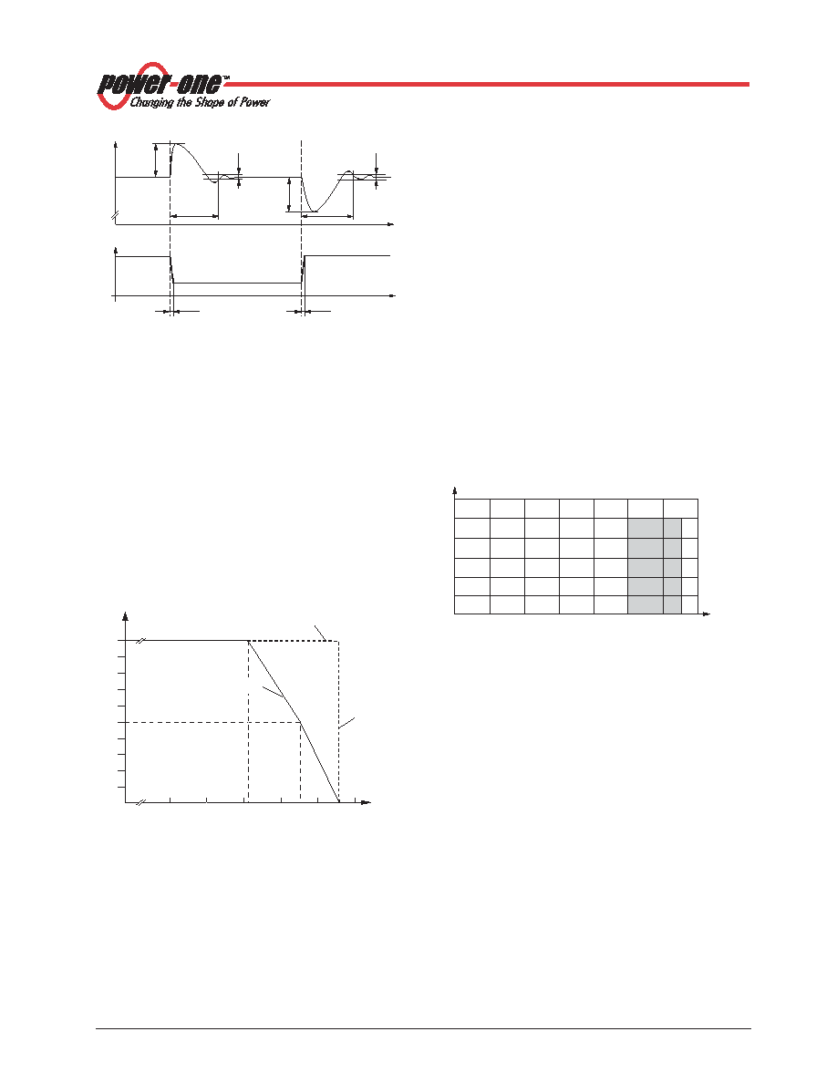
Fig. 3
Dynamic load regulation.
Io/Io nom
1
Vod
t d
DVo I
t
Vo
0
t
≥10 s
05010
相關(guān)PDF資料 |
PDF描述 |
|---|---|
| PSC5A10-9IRD | 1-OUTPUT DC-DC REG PWR SUPPLY MODULE |
| PSC5A12-9LIP | 1-OUTPUT DC-DC REG PWR SUPPLY MODULE |
| PSC158-7IP | 1-OUTPUT DC-DC REG PWR SUPPLY MODULE |
| PSC158-9LIR | 1-OUTPUT DC-DC REG PWR SUPPLY MODULE |
| PSC158-7IRD | 1-OUTPUT DC-DC REG PWR SUPPLY MODULE |
相關(guān)代理商/技術(shù)參數(shù) |
參數(shù)描述 |
|---|---|
| PSC5A11-2 | 功能描述:SWITCHING REGULATOR 56.1W 5.1V RoHS:是 類別:電源 - 板載 >> DC DC Converters 系列:* 標(biāo)準(zhǔn)包裝:5 系列:* |
| PSC5A11-2IR | 制造商:Power-One 功能描述:- Bulk |
| PSC5A12-7IP | 制造商:Power-One 功能描述:- Bulk |
| PSC5A12-7IR | 功能描述:SWITCHING REGULATOR 61.2W 5.1V RoHS:是 類別:電源 - 板載 >> DC DC Converters 系列:* 標(biāo)準(zhǔn)包裝:5 系列:* |
| PSC5A12-7LIR | 制造商:Power-One 功能描述:- Bulk |
發(fā)布緊急采購,3分鐘左右您將得到回復(fù)。