- 您現(xiàn)在的位置:買賣IC網(wǎng) > PDF目錄65987 > PSC5A11-2R (POWER-ONE INC) 1-OUTPUT DC-DC REG PWR SUPPLY MODULE PDF資料下載
參數(shù)資料
| 型號(hào): | PSC5A11-2R |
| 廠商: | POWER-ONE INC |
| 元件分類: | 電源模塊 |
| 英文描述: | 1-OUTPUT DC-DC REG PWR SUPPLY MODULE |
| 文件頁數(shù): | 4/8頁 |
| 文件大小: | 363K |
| 代理商: | PSC5A11-2R |
PSC Series
Switching Regulators, PCB & Chassis
Benign Environment
Edition 4/4.99
4/8
MELCHER
The Power Partners.
Electrical Output Data
General Conditions:
–
TA = 25
°C, unless T
C is specified
– With R or option P, output voltage
Uo = Uo nom at Io nom
Table 3a: Output data
Output
PSC 3E12
PSC 5A11
PSC 129
Characteristics
Conditions
min
typ
max
min
typ
max
min
typ
max
Unit
Uo
Output voltage
Ui nom, Io nom
3.25
3.35
5.05
5.15
11.60
12.40
V
Io
Output current 1
Ui min...Ui max
0
12.0
0
11.0
0
9.0
A
IoL
Output current limitation
TC min...TC max
12.0
15.6
11.0
14.3
9.0
11.7
response 1
uo
Output
Switching freq.
Ui nom, Io nom
55
150
mVpp
voltage
Total
IEC/EN 61204 2
60
160
noise
BW = 20 MHz
DUo U
Static line regulation
Ui min...Ui max, Io nom
100
240
mV
DUo l
Static load regulation
Ui nom, Io = 0...Io nom
100
120
uo d
Dynamic
Voltage deviat.
Ui nom
150
130
360
td
load
Recovery time
Io nom 1/3 Io nom
50
60
s
regulation
IEC/EN 61204 2
aUo
Temperature coefficient
Ui min...Ui max
±1
±2mV/K
DUo/DTC (TC min...TC max)
Io = 0...Io nom
±0.02
%/K
Table 3b: Output data
Output
PSC 159
PSC 249
Characteristics
Conditions
min
typ
max
min
typ
max
Unit
Uo
Output voltage
Ui nom, Io nom
14.50
15.50
23.30
24.70
V
Io
Output current 1
Ui min...Ui max
0
9.0
0
9.0
A
IoL
Output current limitation
TC min...TC max
9.0
11.7
9.0
11.7
response
uo
Output
Switching freq.
Ui nom, Io nom
200
300
mVpp
voltage
Total
IEC/EN 61204 2
210
310
noise
BW = 20 MHz
DUo U
Static line regulation
Ui min...Ui max, Io nom
300
480
mV
DUo l
Static load regulation
Ui nom, Io = 0...Io nom
150
240
uo d
Dynamic
Voltage deviat.
Ui nom
450
700
td
load
Recovery time
Io nom
1/3 Io nom
60
80
s
regulation
IEC/EN 61204 2
aUo
Temperature coefficient
Ui min...Ui max
±3
±5mV/K
DUo/DTC (TC min...TC max)
Io = 0...Io nom
±0.02
%/K
1 See also: Thermal Considerations.
2 See: Technical Information: Measuring and Testing.
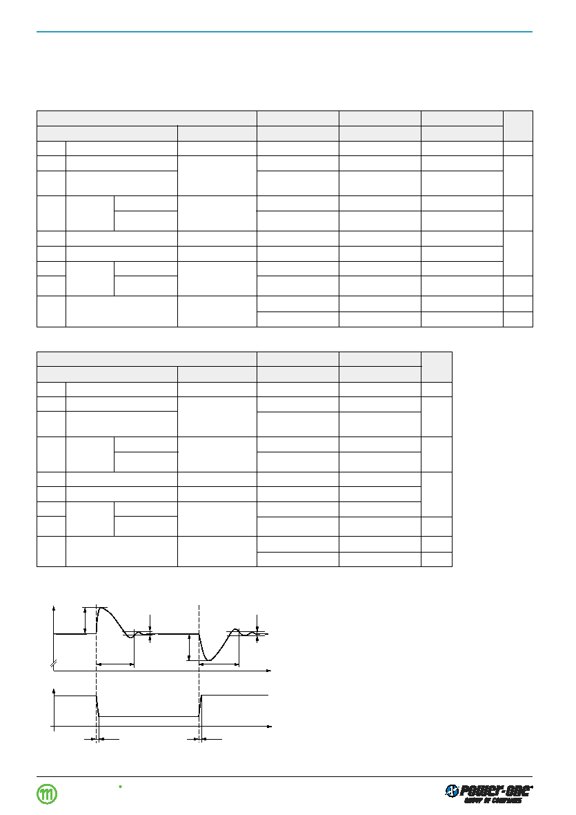
Fig. 3
Dynamic load regulation.
Io/Io nom
1
uod
t d
DUo I
t
Uo
0
t
≥10 s
05010
Parallel and Series Connection
Outputs of equal nominal voltages can be parallel-con-
nected. However, the use of a single unit with higher output
power, because of its power dissipation, is always a better
solution.
In parallel-connected operation, one or several outputs
may operate continuously at their current limit knee-point
which will cause an increase of the heat generation. Conse-
quently, the max. ambient temperature value should be re-
duced by 10 K.
Outputs can be series-connected with any other module. In
series-connection the maximum output current is limited by
the lowest current limitation. Electrically separated source
voltages are needed for each module!
相關(guān)PDF資料 |
PDF描述 |
|---|---|
| PSC5A11-2I | 1-OUTPUT DC-DC REG PWR SUPPLY MODULE |
| PSC159-2R | 1-OUTPUT DC-DC REG PWR SUPPLY MODULE |
| PSC366-7IR | 1-OUTPUT DC-DC REG PWR SUPPLY MODULE |
| PSC128-7IR | 1-OUTPUT DC-DC REG PWR SUPPLY MODULE |
| PSC5A10-7IR | 1-OUTPUT DC-DC REG PWR SUPPLY MODULE |
相關(guān)代理商/技術(shù)參數(shù) |
參數(shù)描述 |
|---|---|
| PSC5A12-7IP | 制造商:Power-One 功能描述:- Bulk |
| PSC5A12-7IR | 功能描述:SWITCHING REGULATOR 61.2W 5.1V RoHS:是 類別:電源 - 板載 >> DC DC Converters 系列:* 標(biāo)準(zhǔn)包裝:5 系列:* |
| PSC5A12-7LIR | 制造商:Power-One 功能描述:- Bulk |
| PSC5A12-9IR | 制造商:Power-One 功能描述:DCDC - Bulk |
| PSC6.3VB1500MJ11 | 制造商:CHEMI-CON 制造商全稱:United Chemi-Con, Inc. 功能描述:Conductive polymer Aluminum solid capacitors |
發(fā)布緊急采購,3分鐘左右您將得到回復(fù)。