- 您現(xiàn)在的位置:買賣IC網(wǎng) > PDF目錄368337 > PT4498C Analog IC PDF資料下載
參數(shù)資料
| 型號: | PT4498C |
| 英文描述: | Analog IC |
| 中文描述: | 模擬IC |
| 文件頁數(shù): | 2/4頁 |
| 文件大小: | 105K |
| 代理商: | PT4498C |
For technical support and more information, see inside back cover or visit www.ti.com
PT4452
—
24V
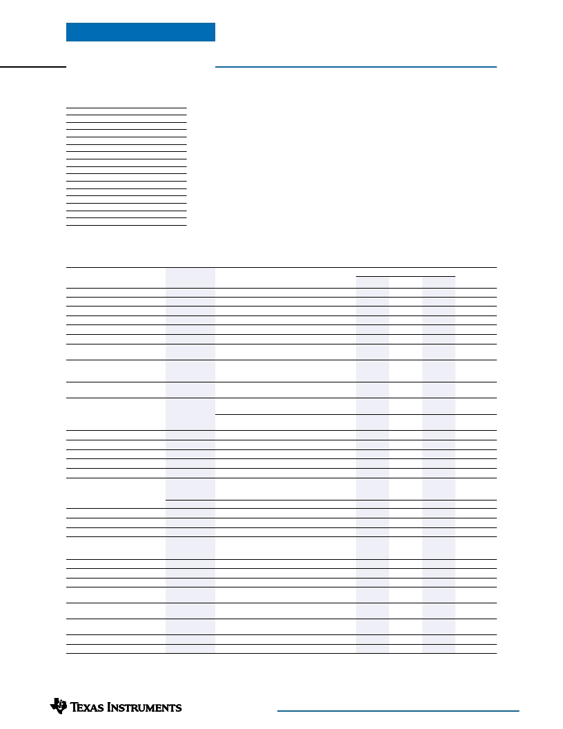
100-W 30-A Programmable
Isolated DC/DC Converter
Programming Information
VID4=1 VID4=0
Vout
2.0V
2.1V
2.2V
2.3V
2.4V
2.5V
2.6V
2.7V
2.8V
2.9V
3.0V
3.1V
3.2V
3.3V
3.4V
3.5V
VID3 VID2 VID1 VID0
1
1
1
1
1
1
1
1
1
0
1
0
1
0
1
0
0
1
0
1
0
1
0
1
0
0
0
0
0
0
0
0
Vout
1.30V
1.35V
1.40V
1.45V
1.50V
1.55V
1.60V
1.65V
1.70V
1.75V
1.80V
1.85V
1.90V
1.95V
2.00V
2.05V
1
1
0
0
1
1
0
0
1
1
0
0
1
1
0
0
1
0
1
0
1
0
1
0
1
0
1
0
1
0
1
0
Logic 0 = Connect to (–)Remote Sense, pin 20
Logic 1 = Open circuit (no pull-up resistors)
Specifications
(Unless otherwise stated, T
a
=25°C, V
in
=24V, V
o
=3.3V, C
o
=0μF, and I
o
=I
o
max)
PT4452
Typ
Characteristic
Symbol
Conditions
Min
Max
Units
Output Current
Input Voltage Range
Set Point Voltage Tolerance
Temperature Variation
Line Regulation
Load Regulation
Total Output Voltage Variation
I
o
V
in
V
o
tol
Reg
temp
Reg
line
Reg
load
V
o
tot
Over V
in
range
Over I
o
Range
0
18
—
—
—
—
—
24
±1
±0.5
±0.1
±0.2
30
36
±1.5
—
±1
±1
A
VDC
%V
o
%V
o
%V
o
%V
o
–40°
≤
T
c
≤
+100°C, I
o
=0
Over V
in
range
Over I
o
range
Includes set-point, line, load,
–40°
≤
T
c
≤
+100°C
I
o
=15A
—
±2
±3
%V
o
Efficiency
η
V
o
=3.3V
V
o
=2.5V
V
o
=1.5V
V
o
>2.0V
V
o
≤
2.0V
—
—
—
—
—
—
—
—
—
—
—
—
270
—
89
87
81
55
45
N/A
1
75
±5
35
±10
125
300
17
—
—
—
75
55
—
—
—
—
—
—
—
350
—
%
V
o
Ripple (pk-pk)
V
r
20MHz bandwidth
mV
pp
Transient Response
t
tr
V
tr
0.1A/μs load step, 50% to 75% I
o
max
V
o
over/undershoot
1A/μs load step, 50% to 100% I
o
max
V
o
over/undershoot
V
in
=18V, shutdown with auto-restart
with PT4495 booster
Shutdown and latch off
Over V
in
range
μs
%V
o
μs
%V
o
A
%
%V
o
kHz
V
Current Limit Threshold
Current Share Tolerance
Over-Voltage Protection
Switching Frequency
Under-Voltage Lockout
Inhibit (Pin 3)
Input High Voltage
Input Low Voltage
Input Low Current
Standby Input Current
Internal Input Capacitance
External Output Capacitance
Isolation Voltage
Capacitance
Resistance
Operating Temperature Range
Over-Temperature Shutdown
Storage Temperature
Reliability
I
lim
thld
I
shr
tol
OVP
s
UVLO
Referenced to –V
in
(pin 2)
V
IH
V
IL
I
IL
I
in
standby
C
in
C
out
2.5
–0.5
—
—
—
0
1500
—
10
-40
—
-40
—
—
–0.2
4
3
—
—
1100
—
—
120
—
Open
(1)
+0.8
—
10
—
10,000
—
—
—
+115
(2)
—
+125
V
mA
mA
μF
μF
V
pF
M
°C
°C
°C
pins 3 & 2 connected
Between +V
o
and –V
o
Input–output/input–case
Input to output
Input to output
Case temperature, over V
in
range
Case temperature, auto reset
—
Per Bellcore TR-332
50% stress, T
a
=40°C, ground benign
Per Mil-Std-883D, method 2002.3,
1mS, half-sine, mounted to a fixture
Mil-Std-883D, Method 2007.2
20-2000Hz, pcb mounted
—
Materials meet UL 94V-0
T
c
OTP
T
s
MTBF
1.4
—
—
10
6
Hrs
Mechanical Shock
—
—
500
—
G’s
Mechanical Vibration
—
Horizontal
—
20
(3)
—
G’s
Weight
Flammability
Notes:
(1) The Inhibit (pin 3) has an internal pull-up, which if left open circuit allows the converter to operate when input power is applied. The open-circuit is
limited to 6.5V. Refer to the application notes for interface considerations.
(2) See Safe Operating Area curves or contact the factory for the appropriate derating.
(3) The case pins on through-hole pin configuration (suffix A) must be soldered. For more information see the applicable package outline drawing.
—
—
—
90
—
grams
相關(guān)PDF資料 |
PDF描述 |
|---|---|
| PT4498N | Analog IC |
| PT4499 | 75V Single N-Channel HEXFET Power MOSFET in a 7-lead D2-Pak package; A IRF2907ZS-7PPBF with Standard Packaging |
| PT4521 | 40V Single N-Channel HEXFET Power MOSFET in a I-Pak package; A IRLU3114ZPBF with Standard Packaging |
| PT4522 | 60V Single N-Channel HEXFET Power MOSFET in a TO-220AB package; A IRFZ44V with Standard Packaging |
| PT4523 | 75V Single N-Channel HEXFET Power MOSFET in a TO-220AB package; A IRFB3077PBF with Standard Packaging |
相關(guān)代理商/技術(shù)參數(shù) |
參數(shù)描述 |
|---|---|
| PT4498N | 功能描述:BOOSTER(PT4484) 20A 48VIN VRT RoHS:是 類別:電源 - 板載 >> 配件 系列:PT4480 標(biāo)準(zhǔn)包裝:1 系列:- 附件類型:測試板 適用于相關(guān)產(chǎn)品:- |
| PT4499 | 制造商:TI 制造商全稱:Texas Instruments 功能描述:100-W 30-A Programmable Isolated DC/DC Converter |
| PT4499A | 功能描述:CONVERTER 30A BOOSTER PT4482 HRZ RoHS:是 類別:電源 - 板載 >> 配件 系列:PT4480 標(biāo)準(zhǔn)包裝:1 系列:- 附件類型:測試板 適用于相關(guān)產(chǎn)品:- |
| PT4499C | 功能描述:CONVERTER 30A BOOSTER PT4482 SMD RoHS:是 類別:電源 - 板載 >> 配件 系列:PT4480 標(biāo)準(zhǔn)包裝:1 系列:- 附件類型:測試板 適用于相關(guān)產(chǎn)品:- |
| PT4499N | 功能描述:DC/DC轉(zhuǎn)換器 30A Current Booster PT4482 DC/DC Conv RoHS:否 制造商:Murata 產(chǎn)品: 輸出功率: 輸入電壓范圍:3.6 V to 5.5 V 輸入電壓(標(biāo)稱): 輸出端數(shù)量:1 輸出電壓(通道 1):3.3 V 輸出電流(通道 1):600 mA 輸出電壓(通道 2): 輸出電流(通道 2): 安裝風(fēng)格:SMD/SMT 封裝 / 箱體尺寸: |
發(fā)布緊急采購,3分鐘左右您將得到回復(fù)。