- 您現(xiàn)在的位置:買賣IC網(wǎng) > PDF目錄370024 > PT4841 15V/3.3V/1.5V 48V-Input 65 Watt Triple-Output DC/DC Converter PDF資料下載
參數(shù)資料
| 型號: | PT4841 |
| 英文描述: | 15V/3.3V/1.5V 48V-Input 65 Watt Triple-Output DC/DC Converter |
| 中文描述: | 15V/3.3V/1.5V 48V的輸入65瓦三輸出DC / DC變換器 |
| 文件頁數(shù): | 9/14頁 |
| 文件大小: | 216K |
| 代理商: | PT4841 |

Application Notes
For technical support and more information, see inside back cover or visit www.ti.com
PT4840 Input/ Output Filter Capacitance Selection
for Excalibur
Triple-Ouput DC/DC Converters
General Requirements
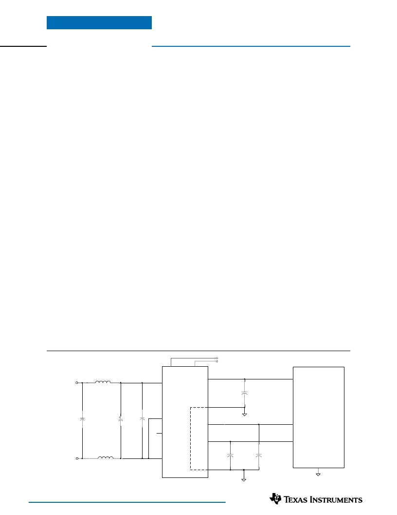
The capacitors on the input bus are optional but may be
required to insure dynamic response to load transients.
The suggested capacitors on the input bus include
ceramic noise attenuation components. The PT4840
series has an internal 1μH input inductor. This inductor
provides an effective input differential noise filter when
1μF ceramic capacitors are connected across the input
terminals. This low impedance filter has an attenuation
factor of typically 15dB.
The output capacitors are all optional and may be used
to optimize dynamic and transient load performance. The
maximum capacitance allowed for each bus is given in the
electrical specification table on p.3.
Input Capacitors
The input capacitors are all optional. The 33μF/100V
electrolytic capacitor should have a minimum ripple
current 400mA. Ripple current and <350m
equivalent
series resistance (ESR) are the major considerations along
with temperature when selecting electrolytic capacitors.
The ceramic capacitors, each 1μF (3
×
0.33μF), X7R type,
have a wide temperature range and are suggested for
noise reduction. The module’s internal inductor and the
external ceramic capacitors form an excellent differential
noise filter. Additional filter components, L
1
and L
2
,
will reject common-mode input noise (
See Figure 1
). A
common-mode choke can also be used to reduce common-
mode noise levels. These optional filter components may
be required to meet FCC Class A limits for conducted
emissions.
PT4840 Series
Figure 1; Optional Capacitor and FIlter Components
IC Chip Set
+V
IN
–
V
IN
+15VDC
+3.3VDC
+1.5VDC
PT4841
1
2
11
15,16
22,23
18
–
20
12,13
3
Vo
1
COM
COM
Vo
2
Vo
3
+V
IN
–
V
IN
EN 1
Vo
2
adj
Vo
3
adj
17
21
C
OUT 1
C
OUT 3
C
OUT 2
4
EN 2
L1
1μH
Optional
L1
1μH
Optional
C
0.33μFx3
Ceramic
C
IN
C
0.33μFx3
Ceramic
Optional Output Capacitors; Vo
1
(Table 1)
The ESR of the 330μF output capacitor for Vo
1
(+15V)
must be
≥
40m
. Electrolytic capacitors have minimal
effect on ripple at frequencies greater than 200kHz but
excellent low-frequency transient response. At the ripple
frequency, ceramic decoupling capacitors improve the re-
sponse to fast transients and reduce any high-frequency
noise components during higher current excursions.
The preferred capacitor part numbers are identified in the
Table 1. The table identifies vendors with acceptable
ESR and ripple current (rms) ratings. The suggested
minimum quantities for Vo
1
are identified. Tantalum
capacitors, rated 30V or greater with an equivalent ESR
of
≥
40m
,
are also recommended for Vo
1
.
Optional Output Capacitors; Vo
2
& Vo
3
(Table 2)
The combined ESR of the output capacitors selected for
Vo
2
and Vo
3
(lower bus voltages) must be
≥
10m
. Low
ESR electrolytic capacitors have minimal effect on ripple
at frequencies greater than 200kHz but excellent low-
frequency transient response. Above the ripple frequency,
ceramic decoupling capacitors improve the response to
fast transients and reduce any high-frequency noise
components during higher current excursions. The
preferred lower ESR type capacitor part numbers for
Vo
2
and Vo
3
are identified in Table 2. The table identifies
vendors with acceptable ESR and ripple current (rms)
ratings. The tantalum and Oscon type capacitors have
both low ESR and stable characteristics. These are
recommended for Vo
2
and Vo
3
in applications where the
temperature range extends below 0°C.
Capacitors from other vendors may also be suitable. The speci-
fications in both tables provide guidance for the selection of
alternative parts. The ripple current (rms) rating and ESR
(Equivalent Series Resistance at 100kHz) are the critical
parameters necessary to insure both optimum regulator and
long term capacitor life cycles.
相關(guān)PDF資料 |
PDF描述 |
|---|---|
| PT4841A | 100V Single N-Channel HEXFET Power MOSFET in a TO-220 FullPak (Iso) package; Similar to IRLI520N with Lead Free Packaging |
| PT4841C | 20V Single N-Channel HEXFET Power MOSFET in a SO-8 package; A IRF7456 with Standard Packaging |
| PT4841N | DC to DC Converter |
| PT4842 | 12V/3.3V/1.8V 48V-Input 62-Watt Triple-Output DC/DC Converter |
| PT4842A | 55V Single N-Channel HEXFET Power MOSFET in a D2-Pak package; Similar to IRF1405S with Lead Free Packaging |
相關(guān)代理商/技術(shù)參數(shù) |
參數(shù)描述 |
|---|---|
| PT4841A | 功能描述:DC/DC轉(zhuǎn)換器 15/3.3/1.5V 48V-Inp 65W 3-Output DC-DC RoHS:否 制造商:Murata 產(chǎn)品: 輸出功率: 輸入電壓范圍:3.6 V to 5.5 V 輸入電壓(標稱): 輸出端數(shù)量:1 輸出電壓(通道 1):3.3 V 輸出電流(通道 1):600 mA 輸出電壓(通道 2): 輸出電流(通道 2): 安裝風(fēng)格:SMD/SMT 封裝 / 箱體尺寸: |
| PT4841C | 制造商:未知廠家 制造商全稱:未知廠家 功能描述:DC to DC Converter |
| PT4841N | 制造商:未知廠家 制造商全稱:未知廠家 功能描述:DC to DC Converter |
| PT4842 | 制造商:未知廠家 制造商全稱:未知廠家 功能描述:12V/3.3V/1.8V 48V-Input 62-Watt Triple-Output DC/DC Converter |
| PT4842A | 功能描述:直流/直流開關(guān)轉(zhuǎn)換器 12/3.3/1.8V 48V-Inp 62W 3-Out DC-DC RoHS:否 制造商:STMicroelectronics 最大輸入電壓:4.5 V 開關(guān)頻率:1.5 MHz 輸出電壓:4.6 V 輸出電流:250 mA 輸出端數(shù)量:2 最大工作溫度:+ 85 C 安裝風(fēng)格:SMD/SMT |
發(fā)布緊急采購,3分鐘左右您將得到回復(fù)。