- 您現(xiàn)在的位置:買賣IC網(wǎng) > PDF目錄370024 > PT4841A 100V Single N-Channel HEXFET Power MOSFET in a TO-220 FullPak (Iso) package; Similar to IRLI520N with Lead Free Packaging PDF資料下載
參數(shù)資料
| 型號(hào): | PT4841A |
| 英文描述: | 100V Single N-Channel HEXFET Power MOSFET in a TO-220 FullPak (Iso) package; Similar to IRLI520N with Lead Free Packaging |
| 中文描述: | DC至DC轉(zhuǎn)換器 |
| 文件頁數(shù): | 5/14頁 |
| 文件大小: | 216K |
| 代理商: | PT4841A |

For technical support and more information, see inside back cover or visit www.ti.com
PT4842
—
48V
65-W Triple Output Isolated DC/DC
Converter for DSL Applications
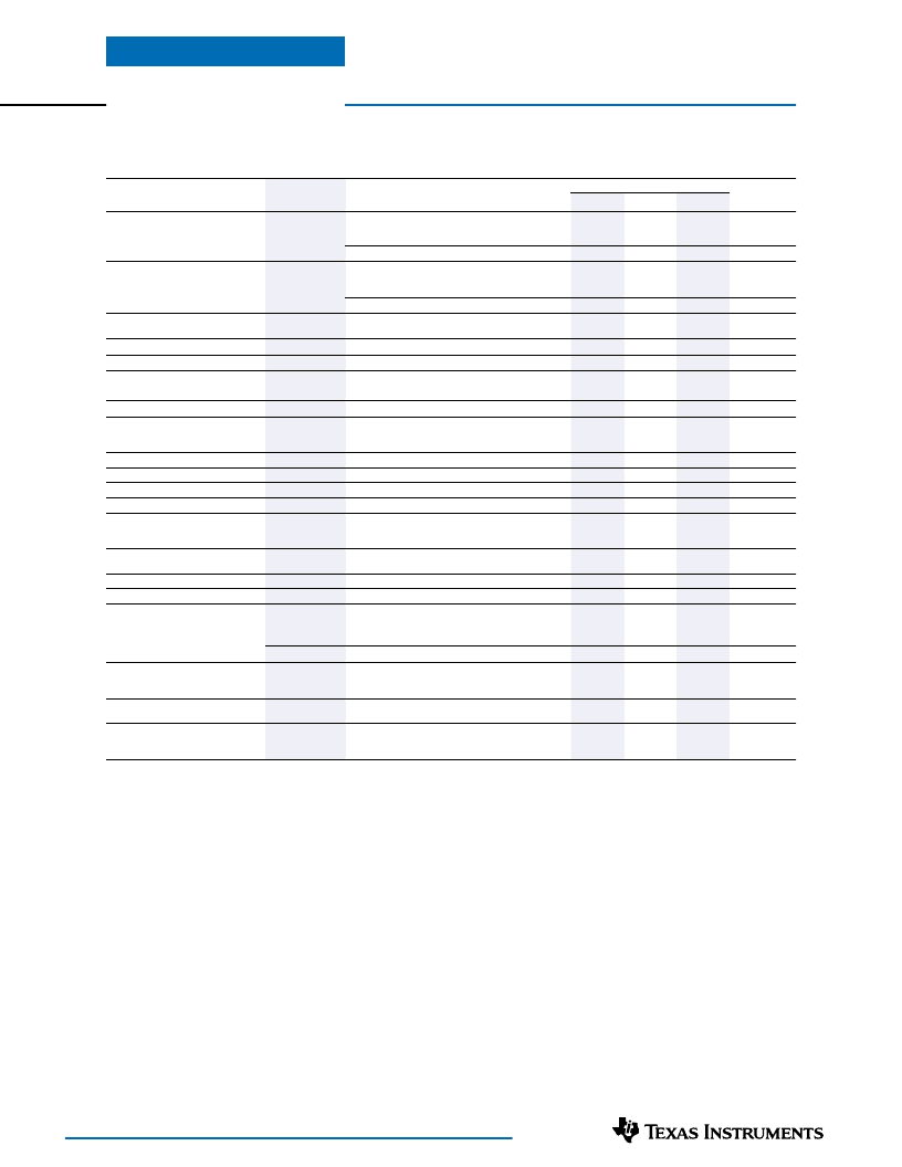
PT4842 Specifications
(Unless otherwise stated, the operating conditions are:- T
a
=25°C, V
in
=48V, and Io
n
=0.5Io
n
max)
PT4842
Typ
Characteristics
Symbols
Conditions
Min
Max
Units
Output Power
P
o
Each output:
Vo
1
( 12V)
Vo
2
(3.3V)
Vo
3
(1.8V)
—
—
—
—
0
0
0
—
—
—
—
36
—
—
—
11.64
3.2
1.74
±10
—
—
—
—
—
—
—
—
—
450
0
2.4
—
—
—
—
—
—
—
—
4
16
200
—
34
32
2
12.0
3.3
1.8
—
0.1
0.2
—
45
20
20
30
5
84
500
—
—
3
9
—
1500
—
0.1
1.5
—
—
—
32.4
20
12.6
62
2.7
6
7
11
—
—
—
75
—
—
—
12.36
3.4
1.86
—
1.0
1.0
1.0
100
50
50
—
—
—
550
0.8
75
5
15
—
—
—
—
—
330
5,000
10,000
(1)
(1)
(1)
W
Total (all three outputs)
(1)
W
A
A
Output Current
I
o
Io
1
( 12V)
Io
2
(3.3V)
Io
3
(1.8V)
(2)
(2)
Maximum (Io
2
+ Io
3
)
(2)
A
Current Limit Threshold
I
LIM
Io
1
A
Io
2
+ Io
3
Over Current Shutdown Delay
(3)
Input Voltage Range
Under Voltage Lockout
t
sd
V
in
V
on
V
off
C
int
V
o
Time period prior to latched shutdown
ms
V
V
V
in
increasing
V
in
decreasing
Internal Input Capacitance
Output Voltage
μF
Vo
1
( 12V)
Vo
2
(3.3V)
Vo
3
(1.5V)
Vo
2
/ Vo
3
V
Output Adjust Range
Line Regulation
Load Regulation
Cross Regulation
V
Ripple/Noise
(0 to 20MHz bandwidth)
V
o
adj
Reg
line
Reg
load
Reg
cross
V
n
%V
o
%V
o
%V
o
%V
o
All outputs, Over V
in
range
All outputs, 0
≤
I
o
≤
I
o
max
Any one output vs. other outputs
C
out
=10μF tantalum capacitor
(4)
Vo
1
( 12V)
Vo
2
(3.3V)
Vo
3
(1.5V)
mV
pp
Transient Response
(5)
t
tr
V
os
η
s
On
Off
25% load step
V
o
over/undershoot
P
o
=P
o
max
Over V
in
and I
o
ranges
Referenced to –V
in
μSec
%V
o
%
kHz
Efficiency
Switching Frequency
On/Off Control
Logic ‘0’
Logic ‘1’
(6)
V
Open cct. voltage
I
stby
V
iso
C
iso
R
iso
V
temp
Input current in ‘Off’ state
—
1500
—
10
—
—
0
0
0
mA
V
pF
M
Primary/Secondary Isolation
Temperature Sense
(7)
Output voltage at temperatures:-
–40°C
100°C
C
o
1
C
o
2
C
o
3
V
External Output Capacitance
(8)
C
out
μF
Notes:
(1) The sum total power delivered from all three regulated outputs, Vo
, Vo
2
, and Vo
3
, cannot exceed 62 watts.
(2) The sum-total current from outputs Vo
, and Vo
cannot exceed 11ADC.
(3) After latched shutdown, the module may be reset by cycling the input power.
(4) The ripple and noise is measured with a 10μF tantalum capacitor across each output.
(5) The transient response is measured with a 25% load step from I
o
=0.5I
o
max, and di/dt =0.2A/μs.
(6) Pins 3 & 4 are diode protected and can be connected to +V
.
(7) Voltage output at “TEMP” pin is defined by the equation:- V
TEMP
= 0.5 + 0.01·T, where T is the sensed temperature in degrees centigrade. See pin
descriptions for more information.
(8) Ultra-low ESR capacitors, such as organic or polymer aluminum electrolytic types, may cause instability. For more information, refer to the application
note regarding capacitor selection.
SLTS142C - DECEMBER 2000 -REVISED SEPTEMBER 2002
相關(guān)PDF資料 |
PDF描述 |
|---|---|
| PT4841C | 20V Single N-Channel HEXFET Power MOSFET in a SO-8 package; A IRF7456 with Standard Packaging |
| PT4841N | DC to DC Converter |
| PT4842 | 12V/3.3V/1.8V 48V-Input 62-Watt Triple-Output DC/DC Converter |
| PT4842A | 55V Single N-Channel HEXFET Power MOSFET in a D2-Pak package; Similar to IRF1405S with Lead Free Packaging |
| PT4842C | DC to DC Converter |
相關(guān)代理商/技術(shù)參數(shù) |
參數(shù)描述 |
|---|---|
| PT4841C | 制造商:未知廠家 制造商全稱:未知廠家 功能描述:DC to DC Converter |
| PT4841N | 制造商:未知廠家 制造商全稱:未知廠家 功能描述:DC to DC Converter |
| PT4842 | 制造商:未知廠家 制造商全稱:未知廠家 功能描述:12V/3.3V/1.8V 48V-Input 62-Watt Triple-Output DC/DC Converter |
| PT4842A | 功能描述:直流/直流開關(guān)轉(zhuǎn)換器 12/3.3/1.8V 48V-Inp 62W 3-Out DC-DC RoHS:否 制造商:STMicroelectronics 最大輸入電壓:4.5 V 開關(guān)頻率:1.5 MHz 輸出電壓:4.6 V 輸出電流:250 mA 輸出端數(shù)量:2 最大工作溫度:+ 85 C 安裝風(fēng)格:SMD/SMT |
| PT4842C | 功能描述:直流/直流開關(guān)轉(zhuǎn)換器 12/3.3/1.8V 48V-Inp 62W 3-Out DC-DC RoHS:否 制造商:STMicroelectronics 最大輸入電壓:4.5 V 開關(guān)頻率:1.5 MHz 輸出電壓:4.6 V 輸出電流:250 mA 輸出端數(shù)量:2 最大工作溫度:+ 85 C 安裝風(fēng)格:SMD/SMT |
發(fā)布緊急采購,3分鐘左右您將得到回復(fù)。