- 您現(xiàn)在的位置:買賣IC網(wǎng) > PDF目錄98066 > PTR08100WVD (TEXAS INSTRUMENTS INC) 10 A SWITCHING REGULATOR, 300 kHz SWITCHING FREQ-MAX, PSIP5 PDF資料下載
參數(shù)資料
| 型號: | PTR08100WVD |
| 廠商: | TEXAS INSTRUMENTS INC |
| 元件分類: | 穩(wěn)壓器 |
| 英文描述: | 10 A SWITCHING REGULATOR, 300 kHz SWITCHING FREQ-MAX, PSIP5 |
| 封裝: | PLASTIC, DSS-5 |
| 文件頁數(shù): | 13/15頁 |
| 文件大小: | 334K |
| 代理商: | PTR08100WVD |
APPLICATION INFORMATION
ADJUSTING THE OUTPUT VOLTAGE
(
)
SET
O
1.182
R
k
V
0.591
=
W
-
4
5
2
1
3
V
O
V
OAdjust
V
I
Inhibit
GND
PTR08100W
R
SET
1%, 0.05 W
C
O
C
I
GND
V
I
V
O
GND
UDG-07116
www.ti.com ....................................................................................................................................................... SLTS284E – AUGUST 2007 – REVISED APRIL 2009
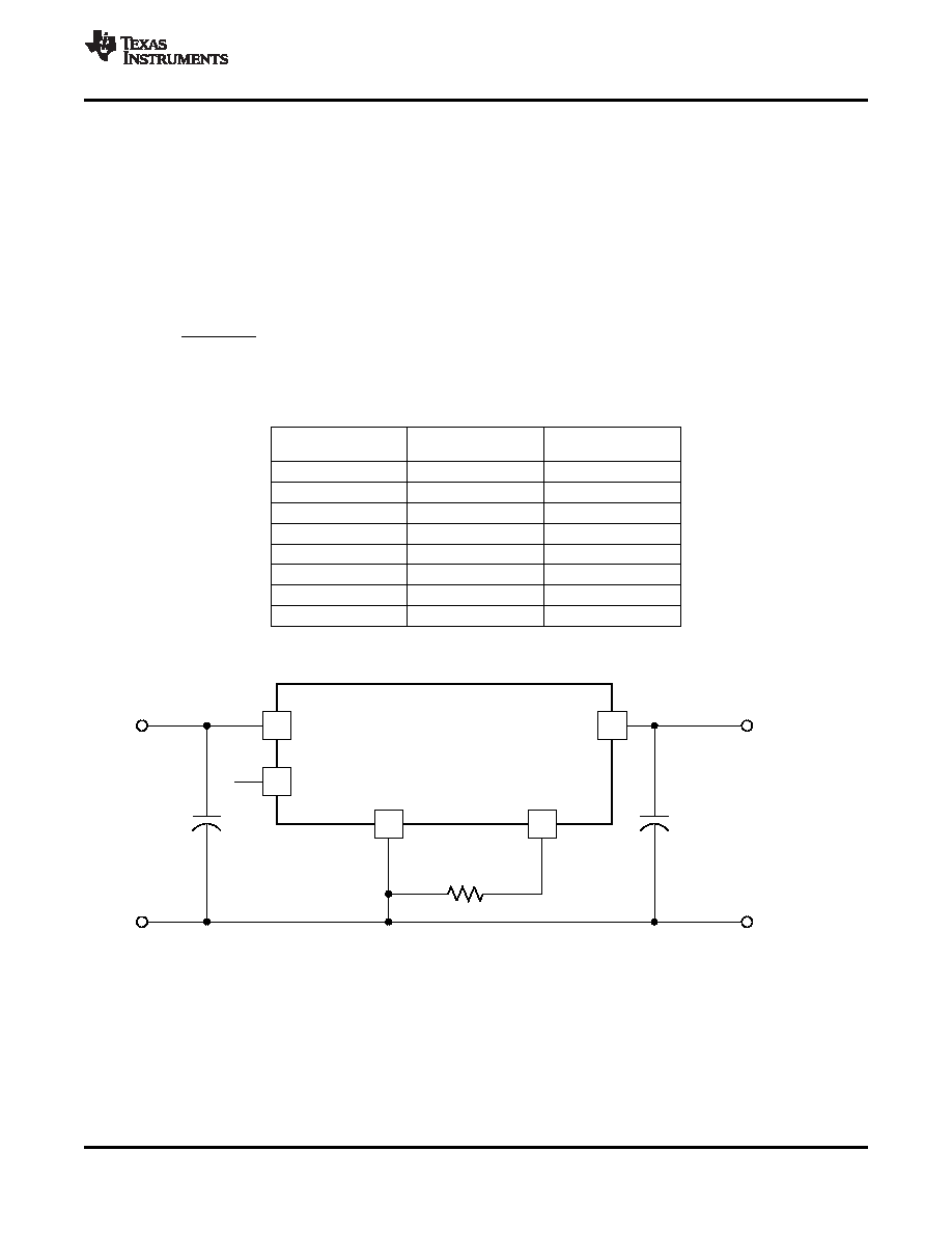
The VOAdjust control (pin 5) sets the output voltage of the PTR08100W product. The adjustment range is from
0.6 V to 5.5 V. The adjustment method requires the addition of a single external resistor, RSET, that must be
connected directly between the VOAdjust and GND pin 3. Table 1 gives the standard external resistor for a
number of common bus voltages, along with the actual voltage the resistance produces.
For other output voltages, the value of the required resistor can either be calculated using the following formula,
or simply selected from the range of values given in Table 2. Figure 12 shows the placement of the required
resistor.
Table 1. Standard Values of RSET for Common Output
Voltages
VO (V)
RSET (k)
VO(V)
(Required)
(Standard Value)
(Actual)
5(1)
0.267
5.018
3.3
0.432
3.327
2.5
0.619
2.501
1.8
0.976
1.802
1.5
1.3
1.500
1.2
1.91
1.210
1
2.87
1.003
0.7
10.7
0.701
(1)
The minimum input voltage is 4.5 V or (VO/0.83) V, whichever is
greater.
(1)
A 0.05-W rated resistor may be used. The tolerance should be 1%, with a temperature stability of 100 ppm/°C (or
better). Place the resistor as close to the regulator as possible. Connect the resistor directly between pins 5 and 3
using dedicated PCB traces.
(2)
The VOAdjust pin must never be connected directly to GND. The minimum resistance between VOAdjust and GND is
limited to 240
.
(3)
Never connect capacitors from VOAdjust to either GND or VO. Any capacitance added to the VOAdjust pin will affect
the stability of the regulator.
Figure 12. VO Adjust Resistor Placement
Copyright 2007–2009, Texas Instruments Incorporated
7
Product Folder Link(s): PTR08100W
相關(guān)PDF資料 |
PDF描述 |
|---|---|
| PTV03020WAH | 1-OUTPUT DC-DC REG PWR SUPPLY MODULE |
| PTV05010WAH | 1-OUTPUT DC-DC REG PWR SUPPLY MODULE |
| PTV08T250WAH | 1-OUTPUT DC-DC REG PWR SUPPLY MODULE |
| PTV08T250WAD | 1-OUTPUT DC-DC REG PWR SUPPLY MODULE |
| PTV12010WAD | 1-OUTPUT DC-DC REG PWR SUPPLY MODULE |
相關(guān)代理商/技術(shù)參數(shù) |
參數(shù)描述 |
|---|---|
| PTR1 | 制造商:Panduit Corp 功能描述: |
| PTR-1 | 制造商:Greenlee Textron Inc 功能描述:REPLACEMENT KIT TIP NAILEATER-1" |
| PTR12 | 制造商:Pentair Technical Products / Hoffman 功能描述:Transformer Rails (2) , fits 1200mm wide, Steel |
| P-TR12 | 制造商:Pentair Technical Products / Hoffman 功能描述:Transformer Rails (2) |
| PTR156F22-2-D | 制造商:ITW Pancon 功能描述: |
發(fā)布緊急采購,3分鐘左右您將得到回復(fù)。