- 您現(xiàn)在的位置:買賣IC網(wǎng) > PDF目錄224941 > PWR-82520-120L Industrial Control IC PDF資料下載
參數(shù)資料
| 型號(hào): | PWR-82520-120L |
| 英文描述: | Industrial Control IC |
| 中文描述: | 工業(yè)控制IC |
| 文件頁數(shù): | 9/12頁 |
| 文件大小: | 361K |
| 代理商: | PWR-82520-120L |

6
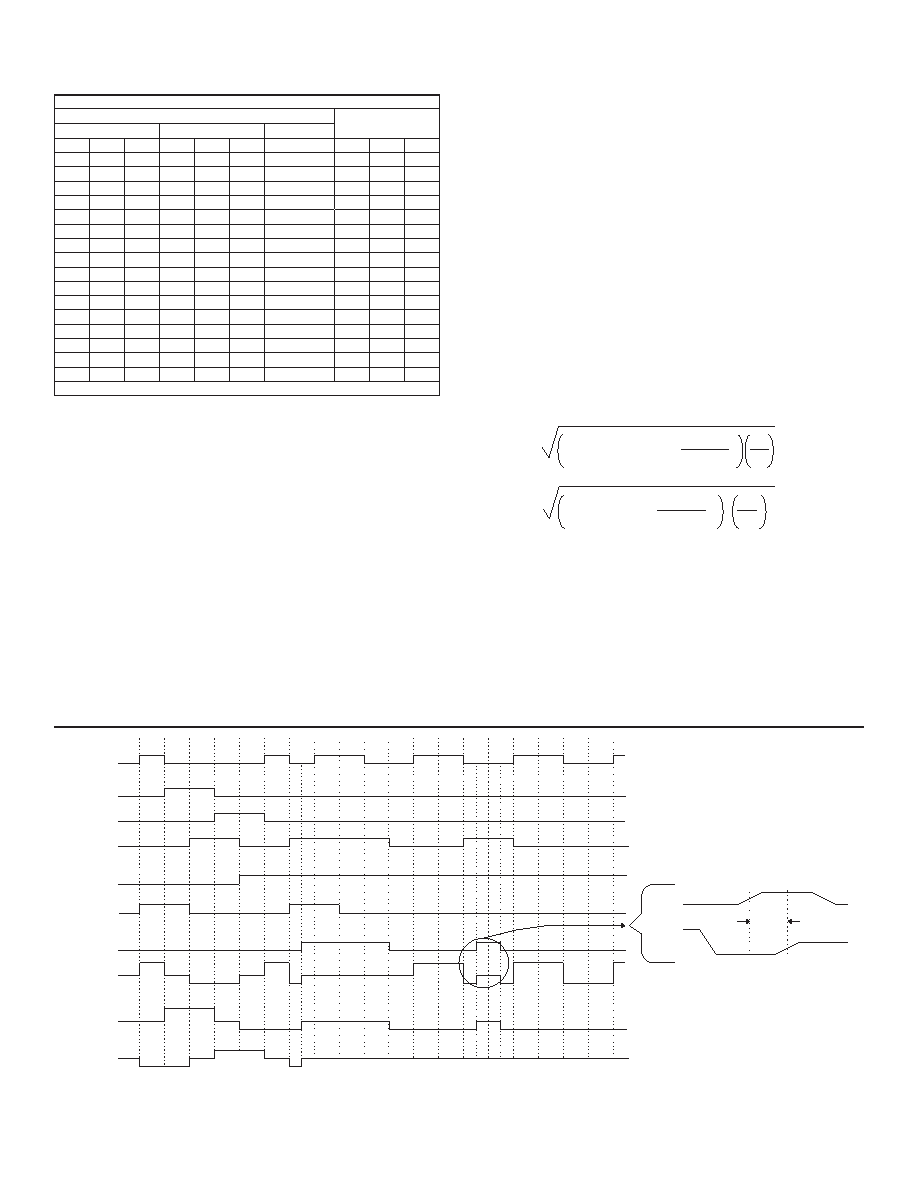
FIGURE 5. SHUT-DOWN (VSd) TIMING RELATIONSHIPS
1
0
1
0
1
0
1
0
1
0
1
0
1
0
H
Z
L
H
Z
L
H
Z
L
1
2
3
4
5
6
7
8
9
10
11
12
13
14
15
16
17
18
19
tSd
V Sd
V OA
H
Z
L
1
0
V UA
V UB
V UC
V LA
V LB
V LC
V Sd
V OA
V OB
V OC
the signals at the VU and VL pins; this ensures the complete
turn-off of any transistor before turning on its associated in-line
transistor.
CHARGE PUMP
The PWR-82330 has an internal charge pump circuit to generate
the drive voltage for the high side N-channel MOSFETs. The
charge pump uses an oscillator to charge an external charge pump
capacitor, Cc, from the Vcc supply. This oscillator will pump the
voltage at pin 48 (+cap) of the hybrid higher than Vcc. The hybrid
high side drivers use this voltage to ensure the proper gate drive.
An external 1 F, 20% capacitor (Cc) is required between pins 48
and 50. If a polarized capacitor is used, the positive terminal
must be connected to pin 48. The voltage rating of Cc must be
2x the maximum value of VCC.
TABLE 3. INPUT/OUTPUT TRUTH TABLE
INPUTS
OUTPUTS
UPPERS
LOWERS
CONTROL
VUA VUB VUC VLA VLB VLC
VSd
VOA VOB VOC
1
0
1
0
H
L
Z
1
0
1
0
H
Z
L
0
1
0
1
0
Z
H
L
0
1
0
1
0
L
H
Z
0
1
0
L
Z
H
0
1
0
1
0
Z
L
H
0
1
0
L
H
0
1
0
1
0
1
0
L
H
L
0
1
0
L
H
1
0
1
0
H
L
1
0
1
0
1
0
H
L
H
1
0
1
0
H
L
0
Z
0
1
0
L
1
0
H
X
1
Z
H = High Level, L= Low Level, X=Irrelevant, Z= High Impedance (OFF)
PWR-82330 POWER DISSIPATION (SEE FIGURE 7)
There are three major contributors to power dissipation in the
motor driver: conduction losses, switching losses, and intrinsic
diode losses.
VCC = +28 V (Bus Voltage)
IoA = 3 A, IOB = 7 A (see FIGURE 7)
ton = 20 s, T = 40 s (period) (see FIGURE 7)
Ron = 0.13
(on-resistance, see TABLE 2, Io = 5 A, Tc=+25°C)
ts1 = 325 ns, ts2 = 325 ns (see FIGURE 7)
fo = 25 kHz (switching frequency)
VF is an intrinsic diode forward voltage, TABLE 2, Io = 5 A
1. Conduction Losses (PC)
Pc = ( Imotor rms)2 x Ron
Pc = (3.63 A)2 x (0.13 W)
Pc = 1.71 Watts
2. Switching Losses (Ps)
Ps = [ Vcc ( IOA (ts1) + IOB (ts2) ) fo] / 2
Ps = [ 28 V ( 3 A (325 ns) + 7 A (325 ns) ) 25 kHz] / 2
Ps = 1.14 Watts
I motor rms=
IOB - IOB (IOB - IOA) +
(IOB - IOA)
ton
2
3
T
I motor rms=
7A - 7A (7A - 3A) +
(7A - 3A)
20us
2
3
40us
相關(guān)PDF資料 |
PDF描述 |
|---|---|
| PWR-82520-120Q | Industrial Control IC |
| PWR-82520-120S | Industrial Control IC |
| PWR-82520-120W | Industrial Control IC |
| PWR-82520-120Y | Industrial Control IC |
| PWR-82520-120Z | Industrial Control IC |
相關(guān)代理商/技術(shù)參數(shù) |
參數(shù)描述 |
|---|---|
| PWR-82520-120Q | 制造商:未知廠家 制造商全稱:未知廠家 功能描述:Industrial Control IC |
| PWR-82520-120S | 制造商:未知廠家 制造商全稱:未知廠家 功能描述:Industrial Control IC |
| PWR-82520-120W | 制造商:未知廠家 制造商全稱:未知廠家 功能描述:Industrial Control IC |
| PWR-82520-120Y | 制造商:未知廠家 制造商全稱:未知廠家 功能描述:Industrial Control IC |
| PWR-82520-120Z | 制造商:未知廠家 制造商全稱:未知廠家 功能描述:Industrial Control IC |
發(fā)布緊急采購,3分鐘左右您將得到回復(fù)。