- 您現(xiàn)在的位置:買賣IC網(wǎng) > PDF目錄361253 > QCH28515T (MS KENNEDY CORP) 30W Triple DC-DC Converter(輸出功率30W的三輸出DC-DC轉(zhuǎn)換器) PDF資料下載
參數(shù)資料
| 型號: | QCH28515T |
| 廠商: | MS KENNEDY CORP |
| 元件分類: | 基準電壓源/電流源 |
| 英文描述: | 30W Triple DC-DC Converter(輸出功率30W的三輸出DC-DC轉(zhuǎn)換器) |
| 中文描述: | 3-OUTPUT 30 W DC-DC REG PWR SUPPLY MODULE |
| 封裝: | HERMETIC SEALED, DIP-10 |
| 文件頁數(shù): | 6/7頁 |
| 文件大小: | 156K |
| 代理商: | QCH28515T |

SYNCHRONIZATION
The synch pin allows the converter to be synchronized in
frequency and phase with an external signal. This signal
should be TTL compatable (0.8 max V
INL
and 2.0 V min V
INH
).
Overdrive up to 10V is not harmful. Transient voltage withstand
is ± 50V with respect to input common. The frequency applied
to this pin must be between 350 and 600 kHz with duty factor
anywhere from 20 to 80 percent.
SHUTDOWN
The shutdown pin turns off the power conversion circuits and
puts the converter in standby mode. The shutdown pin is
referenced to the input common pin. In standby mode the
converter only draws 2.2 mA typical (5.0 mA maximum) input
current from V
IN
. For normal operation this pin should be open
circuited and allowed to float. For shutdown pull this pin below
1 volt. The maximum open circuit voltage that will appear on
this pin is 15 volts. See graphs for typical time response of the
converter to assert and release shutdown.
QCH28515T/RCH28515T
APPLICATION INFORMATION
LOAD FAULT RESPONSE
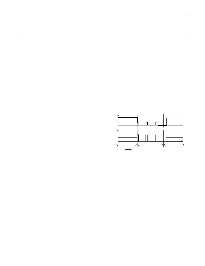
The QCH28515T/RCH28515T family of DC-DC convert-
ers use a common fault protection approach. Load fault
conditions include short-circuit and overload conditions. The
QCH28515T/RCH28515T converters respond to load faults
on the main output (+5V) by turning off all power conversion
circuits for a period of time and then attempting to restart. The
figure below shows the fault protection response to an output
overload, the turn on plus detect fault time is typically two
milliseconds and the off time is typically twenty milliseconds.
The net "on" duty factor during a fault is only 10 percent,
resulting in low converter dissipation and immunity from
overheating at 125°C. An added benefit to this method is that
the amount of output current that defines a fault is pro-
grammed to increase by 1.5X during the first few hundred
microseconds of operation after power-up, load fault recov-
ery or release of the shutdown pin. This allows QCH28515T/
RCH28515T converters to bring up capacitive and other
difficult loads more reliably than some competing converters.
NORMAL
TIME
NORMAL
LOAD FAULT
Vo
I
o
The auxiliary outputs have individual overcurrent protection
and independent fault protection. A rapid response thermal
shutdown feature adds to the reliability of the converter by
protecting each auxiliary output from load faults. Substantial
current may drawn from either auxiliary output but is limited to
safe levels by independent current sensing circuitry on each.
If the fault or overload continues for extended periods the
thermal shut down circuitry will cycle the output to limit the
maximum internal hotspot temperature to a safe level.
6
PRELIMINARY Rev. - 5/01
相關PDF資料 |
PDF描述 |
|---|---|
| QCK3 | PHOTODARLINGTON OPTICAL INTERRUPTER SWITCH |
| QCK4 | PHOTODARLINGTON OPTICAL INTERRUPTER SWITCH |
| QCK3 | SLOTTED OPTICAL SWITCH |
| QCK4 | SLOTTED OPTICAL SWITCH |
| QCK5 | PHOTOTRANSISTOR OPTICAL INTERRUPTER SWITCH |
相關代理商/技術參數(shù) |
參數(shù)描述 |
|---|---|
| QCHW2060H | 制造商:Eaton Corporation 功能描述:QCHW 2 POLE 60 aMP |
| QCHW2070 | 制造商:Eaton Corporation 功能描述:QCHW 2 Pole 70 Amp Breaker |
| QCHW2100 | 制造商:Eaton Corporation 功能描述:QCHW 2 Pole 100 amp |
| QCHW3050H | 制造商:Eaton Corporation 功能描述:Breaker, Mini, 3 Pole, 50A, 240V |
| QCHW3080HT | 制造商:Eaton Corporation 功能描述:3 POLE 80 AMP QCHW BREAKER WITH RING TONGUE CONN |
發(fā)布緊急采購,3分鐘左右您將得到回復。