- 您現(xiàn)在的位置:買賣IC網(wǎng) > PDF目錄296934 > QL16X24B-XCG144C (QUICKLOGIC CORP) FPGA, 384 CLBS, 4000 GATES, CPGA144 PDF資料下載
參數(shù)資料
| 型號(hào): | QL16X24B-XCG144C |
| 廠商: | QUICKLOGIC CORP |
| 元件分類: | FPGA |
| 英文描述: | FPGA, 384 CLBS, 4000 GATES, CPGA144 |
| 封裝: | CERAMIC, PGA-144 |
| 文件頁數(shù): | 9/10頁 |
| 文件大?。?/td> | 1047K |
| 代理商: | QL16X24B-XCG144C |
QL16x24B
4-28
ABSOLUTE MAXIMUM RATINGS
Supply Voltage ................................. –0.5 to 7.0V
Storage Temperature ....... –65°C to + 150°C
Input Voltage ....................... –0.5 to VCC +0.5V
Lead Temperature ...................................300°C
ESD Pad Protection .................................. ±2000V
DC Input Current...................................... ±20 mA
Latch-up Immunity ................................. ±200 mA
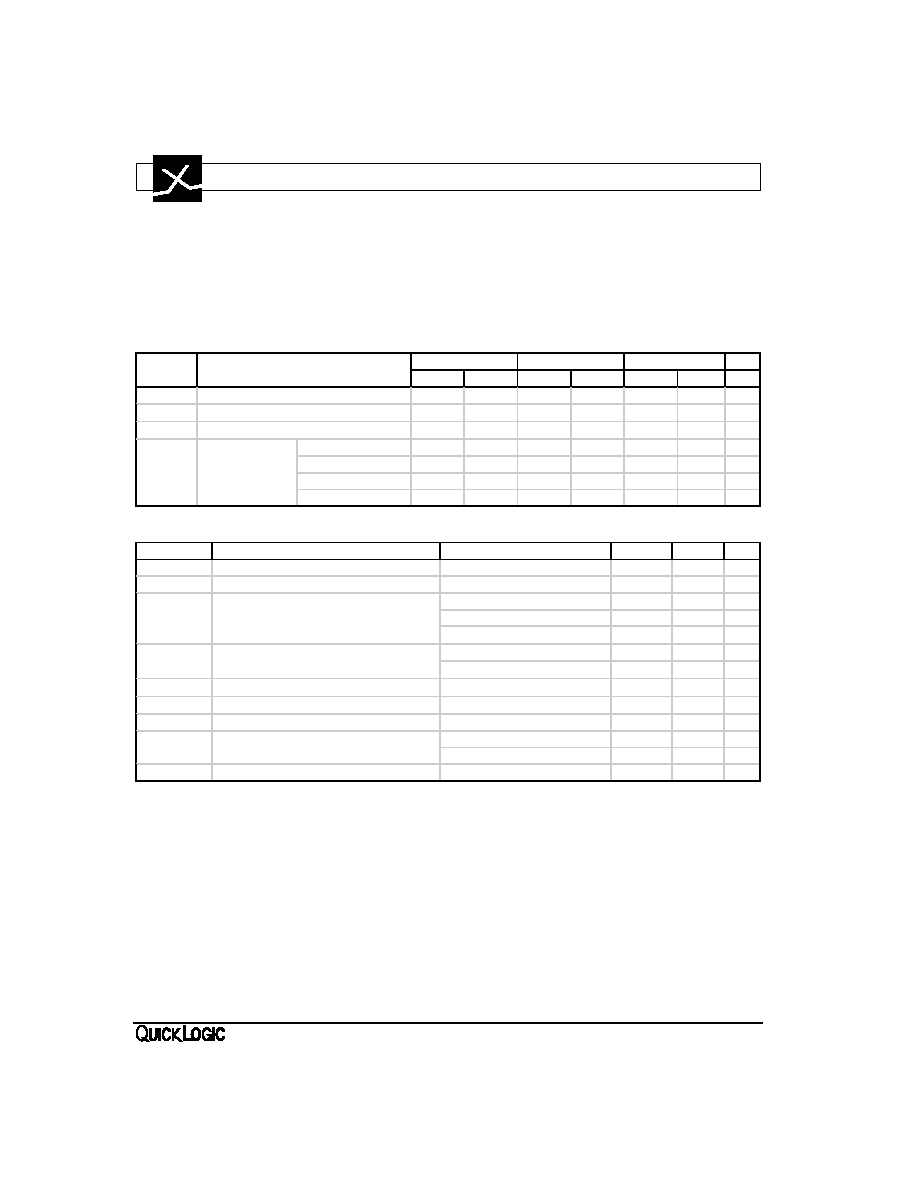
OPERATING RANGE
Symbol
Parameter
Military
Industrial
Commercial
Unit
Min
Max
Min
Max
Min
Max
VCC
Supply Voltage
4.5
5.5
4.5
5.5
4.75
5.25
V
TA
Ambient Temperature
-55
-40
85
0
70
°C
TC
Case Temperature
125
°C
-X Speed Grade
0.4
2.75
0.46
2.55
K
Delay Factor
-0 Speed Grade
0.39
1.82
0.4
1.67
0.46
1.55
-1 Speed Grade
0.39
1.56
0.4
1.43
0.46
1.33
-2 Speed Grade
0.4
1.35
0.46
1.25
DC CHARACTERISTICS over operating range
Symbol
Parameter
Conditions
Min
Max
Unit
VIH
Input HIGH Voltage
2.0
V
VIL
Input LOW Voltage
0.8
V
IOH = -4 mA
3.7
V
VOH
Output HIGH Voltage
IOH = -8 mA
2.4
V
IOH = -10
A
VCC-0.1
V
VOL
Output LOW Voltage
IOL = 12 mA*
0.4
V
IOL = 10
A
0.1
V
II
Input Leakage Current
VI = VCC or GND
-10
10
A
IOZ
3-State Output Leakage Current
VI = VCC or GND
-10
10
A
CI
Input Capacitance [1]
10
pF
IOS
Output Short Circuit Current [2]
VO = GND
-10
-80
mA
VO = VCC
30
140
mA
ICC
D.C. Supply Current [3]
VI, VIO = VCC or GND
10
mA
*IOL = 12 mA for commercial range only. IOL = 8 mA for the industrial and military ranges.
Notes:
[1]
Capacitance is sample tested only. CI = 20 pF max on I/(SI).
[2]
Only one output at a time. Duration should not exceed 30 seconds.
[3]
Commercial temperature grade only. Maximum Icc for industrial grade is 15mA and for military grade is
20 mA. For AC conditions use the formula described in the Section 9 — Power vs Operating Frequency.
[4]
Stated timing for worst case Propagation Delay over process variation at VCC = 5.0V and TA = 25°C.
Multiply by the appropriate Delay Factor, K, for speed grade, voltage and temperature settings as specified
in the Operating Range.
[5]
These limits are derived from a representative selection of the slowest paths through the pASIC logic cell
including net delays. Worst case delay values for specific paths should be determined from timing analysis
of your particular design .
相關(guān)PDF資料 |
PDF描述 |
|---|---|
| QL16X24B-XCG144I | FPGA, 384 CLBS, 4000 GATES, CPGA144 |
| QL16X24B-XPF100C | FPGA, 384 CLBS, 4000 GATES, PQFP100 |
| QL16X24B-XPF144C | FPGA, 384 CLBS, 4000 GATES, PQFP144 |
| QL16X24B-XPL84C | FPGA, 384 CLBS, 4000 GATES, PQCC84 |
| QL16X24BH1CG144I | ASIC |
相關(guān)代理商/技術(shù)參數(shù) |
參數(shù)描述 |
|---|---|
| QL16X24B-XCG144I | 制造商:未知廠家 制造商全稱:未知廠家 功能描述:Field Programmable Gate Array (FPGA) |
| QL16X24B-XCG144M | 制造商:未知廠家 制造商全稱:未知廠家 功能描述:Field Programmable Gate Array (FPGA) |
| QL16X24B-XCG144M/883C | 制造商:未知廠家 制造商全稱:未知廠家 功能描述:Field Programmable Gate Array (FPGA) |
| QL16X24B-XPF100C | 制造商:未知廠家 制造商全稱:未知廠家 功能描述:Field Programmable Gate Array (FPGA) |
| QL16X24B-XPF100I | 制造商:未知廠家 制造商全稱:未知廠家 功能描述:Field Programmable Gate Array (FPGA) |
發(fā)布緊急采購,3分鐘左右您將得到回復(fù)。