- 您現(xiàn)在的位置:買賣IC網(wǎng) > PDF目錄373223 > R1250V2.31A-E2 Analog IC PDF資料下載
參數(shù)資料
| 型號: | R1250V2.31A-E2 |
| 英文描述: | Analog IC |
| 中文描述: | 模擬IC |
| 文件頁數(shù): | 3/13頁 |
| 文件大小: | 127K |
| 代理商: | R1250V2.31A-E2 |

12345
Rev. 1.10 - 3 -
n
PIN DESCRIPTION
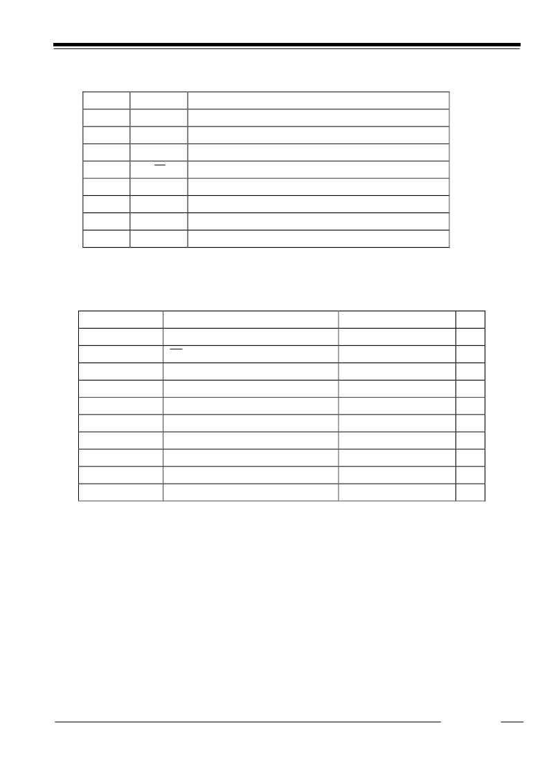
Pin No.
Symbol
Description
1
C
P+
C
P
(Capacitor for Charge Pump) Positive Power Supply Pin
2
GND
Ground Pin
3
C
P
-
C
P
(Capacitor for Charge Pump) Negative Power Supply Pin
4
CE
Chip Enable Pin (active at “L”)
5
NC
No Connection Pin
6
V
REF
Output Pin for Reference Voltage(*Note1)
7
V
OUT
Output Pin for Negative Regulator
8
V
IN
Power Supply Pin
*Note1 V
REF is just a monitoring pin, therefore remain open. Do not connect any load. Refer to Technical Notes.
Q
ABSOLUTE MAXIMUM RATINGS
(GND=0V)
Symbol
Item
Rating
Unit
V
IN
V
IN
Supply Voltage
-0.3 to 7.5
V
V
CE
CE Pin Input Voltage
-0.3 to V
IN
+0.3
V
V
P+
C
P+
Pin Input Voltage
-0.3 to V
IN
+0.3
V
V
REF
V
REF
Pin Voltage
-0.3 to V
IN
+0.3
V
V
P-
C
P-
Pin Input Voltage
V
IN
-12 to +0.3
V
V
OUT
V
OUT
Pin Voltage
V
IN
-12 to +0.3
V
I
OUT
Output Current
200
mA
P
D
Power Dissipation*
NOTE1
490
mW
Topt
Operating Temperature Range
-40 to +85
q
C
Tstg
Storage Temperature Range
-55 to +125
q
C
*Note1: Power dissipation is specified under our specified condition.
Conditions;
Evaluation Board Dimensions: 50mm
′
50mm
′
1.6mm
Material: Glass Epoxy (FR-4)
Reverse side of the evaluation board: Plane Copper
Surface of the evaluation board: Land pattern and Wiring
相關PDF資料 |
PDF描述 |
|---|---|
| R1250V2.41A- | Analog IC |
| R1250V2.41A-E2 | Analog IC |
| R1250V3.31A-E2 | Analog IC |
| R1250V3.41A- | Analog IC |
| R1250V3.41A-E2 | Analog IC |
相關代理商/技術參數(shù) |
參數(shù)描述 |
|---|---|
| R1250V3.01A- | 制造商:未知廠家 制造商全稱:未知廠家 功能描述:Analog IC |
| R1250V3.01A-E2 | 制造商:未知廠家 制造商全稱:未知廠家 功能描述:Analog IC |
| R1250V3.11A- | 制造商:未知廠家 制造商全稱:未知廠家 功能描述:Analog IC |
| R1250V3.11A-E2 | 制造商:未知廠家 制造商全稱:未知廠家 功能描述:Analog IC |
| R1250V3.21A- | 制造商:未知廠家 制造商全稱:未知廠家 功能描述:Analog IC |
發(fā)布緊急采購,3分鐘左右您將得到回復。