- 您現(xiàn)在的位置:買賣IC網(wǎng) > PDF目錄368422 > R1A7G (DAESAN ELECTRONICS CORPORATION) CURRENT 1.0 AMPERES VOLTAGE 50 TO 1000 VOLTS PDF資料下載
參數(shù)資料
| 型號(hào): | R1A7G |
| 廠商: | DAESAN ELECTRONICS CORPORATION |
| 英文描述: | CURRENT 1.0 AMPERES VOLTAGE 50 TO 1000 VOLTS |
| 中文描述: | 1.0安培電流電壓50至1000伏特 |
| 文件頁(yè)數(shù): | 1/2頁(yè) |
| 文件大?。?/td> | 109K |
| 代理商: | R1A7G |
R1A1G THRU R1A7G
Features
Mechanical Data
· The plastic package carries Underwrites Laboratory
Flammability Classification 94V-0
· High current capability
· Low reverse leakage
· Glass passivated junction
· Low forward voltage drop
· High temperature soldering guaranteed : 350
0.375"(9.5mm) lead length, 5 lbs, (2.3kg) tension
/10 seconds,
Maximum Ratings And Electrical Characteristics
· Case : R-1 molded plastic body
· Terminals : Lead solderable per MIL-STD-750,
method 2026
· Polarity : Color band denotes cathode end
· Mounting Position : Any
· Weight : 0.007 ounce, 0.19 grams
(Ratings at 25
load. For capacitive load, derate by 20%)
ambient temperature unless otherwise specified, Single phase, half wave 60Hz, resistive or inductive
Notes:
(1) Measured at 1MHz and applied reverse voltage of 4.0V DC.
(2) Thermal resistance from junction to ambient and from junction to lead at 0.375"(9.5mm) lead length, P.C.B. mounted
CURRENT 1.0Ampere
VOLTAGE 50 to 1000 Volts
Maximum recurrent peak reverse voltage
Maximum RMS voltage
Maximum DC blocking voltage
Volts
Peak forward surge current 8.3ms half sing
wave superimposed on rated load
(JEDEC method)
V
DC
Maximum average forward rectified current
0.375"(9.5mm) lead length T
A
=25
Maximum instantaneous forward voltage
at 1.0A
V
RRM
Volts
Symbols
Units
1.0
V
F
V
RMS
1.0
Amps
25.0
I
FSM
T
J
T
STG
50.0
-65 to +175
Volts
Amp
Maximum reverse
current at rated voltage
Typical thermal resistance (Note 2)
Typical junction capacitance (Note 1)
Operating and Storage temperature Range
50
R1A1G
35
50
5.0
50.0
Volts
A
/W
pF
I
(AV)
I
R
R
JA
T
A
=25
T
A
=100
15.0
C
J
100
R1A2G
70
100
200
R1A3G
140
200
400
R1A4G
280
400
600
R1A5G
420
600
800
R1A6G
560
800
1000
R1A7G
700
1000
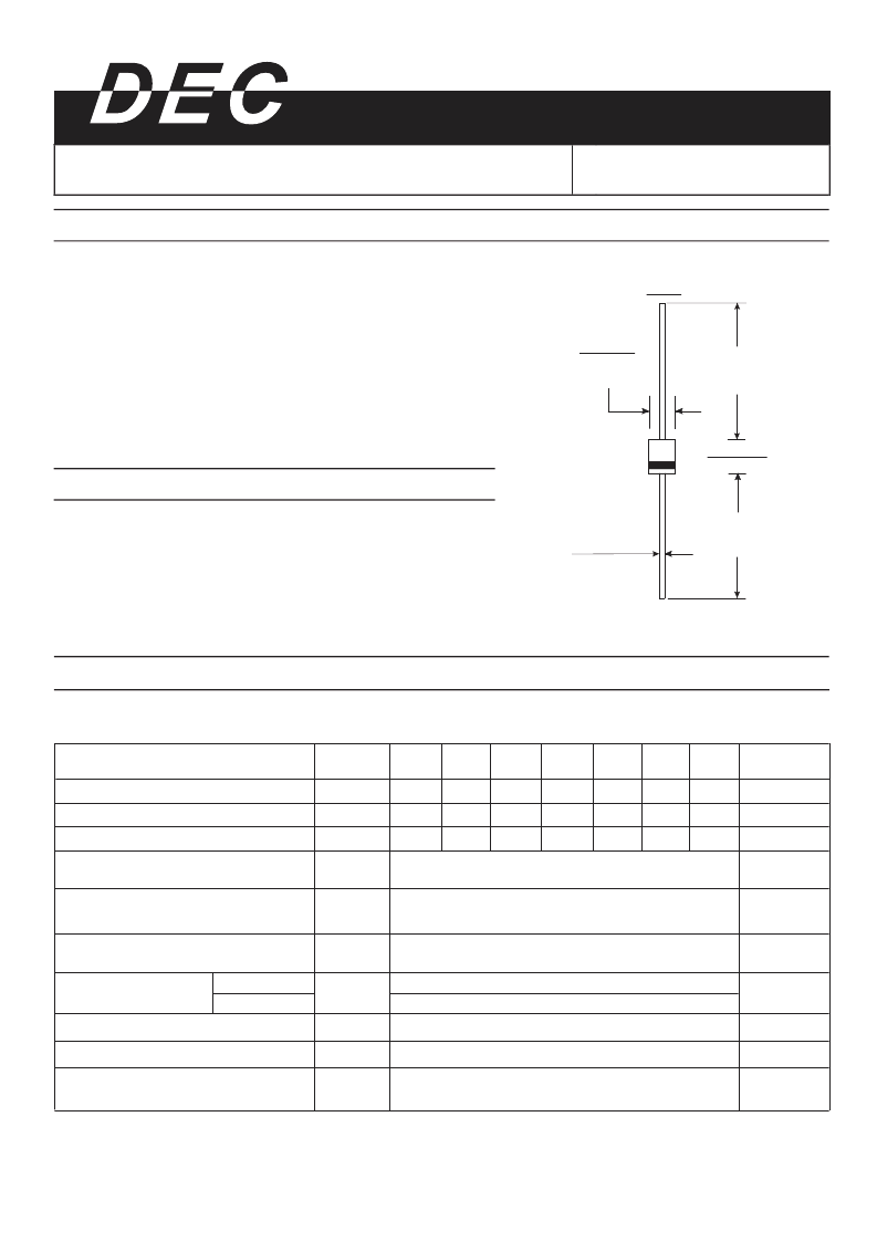
Dimensions in inches and (millimeters)
R-1
0.787(20.0)
MIN.
0.787(20.0)
MIN.
0.126(3.2)
0.106(2.7)
0.025(0.65)
0.021(0.55)
DIA.
0.102(2.6)
0.091(2.3)
DIA.
相關(guān)PDF資料 |
PDF描述 |
|---|---|
| R1A2 | CURRENT 1.0 AMPERES VOLTAGE 50V TO 1000 VOLTS |
| R1A3 | CURRENT 1.0 AMPERES VOLTAGE 50V TO 1000 VOLTS |
| R1A4 | CURRENT 1.0 AMPERES VOLTAGE 50V TO 1000 VOLTS |
| R1A5 | CURRENT 1.0 AMPERES VOLTAGE 50V TO 1000 VOLTS |
| R1A6 | CURRENT 1.0 AMPERES VOLTAGE 50V TO 1000 VOLTS |
相關(guān)代理商/技術(shù)參數(shù) |
參數(shù)描述 |
|---|---|
| R1A-N16-2001B | 制造商:KOA Speer Electronics Inc 功能描述: |
| R1AS-12V | 制造商:Panasonic Electric Works 功能描述: |
| R1AS-6V | 制造商:Panasonic Electric Works 功能描述: |
| R1ASD-5V | 制造商:Panasonic Electric Works 功能描述: |
| R1ASL2D-12V | 制造商:Panasonic Electric Works 功能描述: |
發(fā)布緊急采購(gòu),3分鐘左右您將得到回復(fù)。